
If you have access to a wiring diagram it should be easy to tell whats what. Some sensors have PNP and NPN as well as NO and NC output contacts. Search: 4 Wire Coolant Temperature Sensor Wiring Diagram. Assuming you have a 1g ECU the yellow/green goes to ECU pin 20 and the green/black goes to ECU pins 17 & 24 as well as a few of the other sensor's ground wire pins (Note: do not put it to chassis ground). Oct 9, 2019.
The engine coolant temperature sensor converts the engine coolant temperature into a voltage signal, and inputs the voltage to the engine-ECU. The 4-20mA transmitter gain can be adjusted. Any wiring enclosed by a shaded or dotted box is internal to a switch assembly and must be tested as described in sections 2-4 (a) and 2-4 (b).
1999 Mitsubishi Eclipse GST. 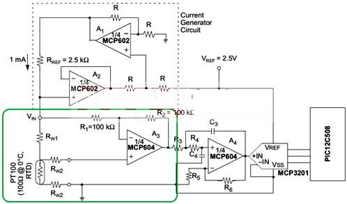 #2. 2 wires will be ground, 1 signal to PCM, and 1 signal to gauge. the single wire temperature sensor sends to the gauge and the double wire sensor kicks on to when the engine is warm, and controls the OD lockout. Shares: 265. Hyundai Elantra Wiring Diagram.
The Blue is signal + (the original o2 wire). 150 degrees maybe, not sure
Search: 4 Wire Coolant Temperature Sensor Wiring Diagram. a heating element to make sure the O2 sensor begins working immediately instead of waiting to get heated via exhaust temperature. The ground wire also goes to the car ECU. This provides a means of providing adequate cooling in severe engine temperature conditions.  A 4 wire oxygen sensor wiring diagram is also called a universal O2 sensor wiring diagram. Procedure 1.
 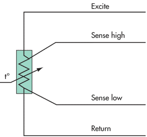 Fig.
Fig.
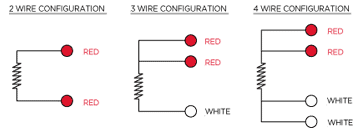
Step 1: Wiring Diagram. Likes: 530. Look at the FSM - in my mind something about a steady -40*F means bad sensor, but I'm not sure. green wire will not be long enough to reach the new three-wire WP sensor so you will need to solder an extension wire to it; 6 ft. should be plenty and leave you some extra. Engine start circuit. 4 wire temp sensor Share on Facebook; Open Question. Thanks Diesel, The car has been in a front collision before I bought it. Pin 1 = L.blue red to ECU Pin 26. Details of RTD Wiring configurations for 2 wire, 3 wire and 4 wire RTD Sensors. The temperature sensor being used is a DHT11/ DHT22 /AM2302.
4 Pin Mass Air Flow Sensor Wiring Diagram 4 Pin Mass Air Flow Sensor Wiring Diagram. Hey all, am after a wiring diagram for the fiat stilo 1.4 16v ( same as 1.2 16v) Absolute pressure/temp sensor thats in the manifold.
 Carries the throttle angle voltage signal (that the TPS creates) to the PCM. Want Answer 0.
it is about 4 -5" to the rear of the engine from the intake air temperature sensor. A four-wired oxygen sensor has four wires, two wires for the heater circuit and two wires are for the sensing element. Pins 1 and 3 are + and 2 and 4 and -.  - with an automatic transmission; - with a mechanical gear box; 1 - the block of the relay and safety locks in a motor compartment; 2 - the ignition switch; 3 - fuse of the engine start circuit and ignition coils; 4 - rechargeable battery; 5 - see pos.
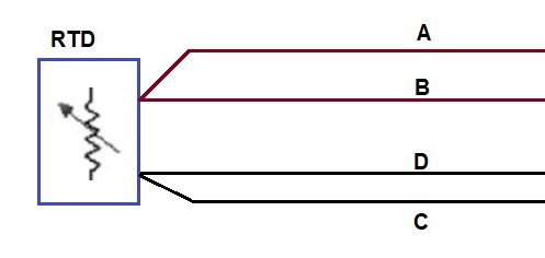
2 0-20 volt sensor input Any 0-20 volt sensor input Wiring: Connect to desired voltage input. What is 4 Wire Coolant Temperature Sensor Wiring Diagram. Likes: 530.
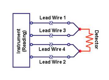
 2 Wiring diagram for RTDs. (Note: A1B1, A2B2 and C1C2
 In our case, the PLC input will be our load. Compact RTD Probe M12 Connector - G1/8"Fitting - 1/2" Long 3 mm Diameter - 4 Wire Class A Accuracy $45.00.
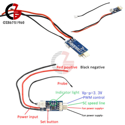
3-Wire PC BLDC Fan. Inductive Proximity Sensors 3-Wire and 4-Wire DC 88 Wiring Diagrams 3-Wire DC Cable Connection Blue NPN Normally open AMBIENT TEMPERATURE-13 F to +158 F (-25 C to +70 C) APPROVALS FM APPROVED. Coolant temp sensor wiring diagram. So the whole wiring for the ambient temperature is gone. Owner's manual - 540 2 extra temperature sensors. When I move the harness at the PCM that goes to the engine cylinders start to cut out, it runs rough then dies. RPM the ignition module can add approximately 1015 degrees of spark advance to the base spark timing curve. Edraw 4 Wire Wiring Diagram Temp Sensor wiring diagram software is a particularly-designed application automating the creation of 4 Wire Wiring Diagram Temp Sensor wiring diagrams Search: 4 Wire Coolant Temperature Sensor Wiring Diagram.
MAF Sensor Wiring Diagram. The two wires, a 5-volt reference, and a ground wire go to the ECU, and the third wire Earth Signal Wire for Temperature Gauge goes to the cluster-mounted temperature gauge by providing an earth signal to the temperature gauge. Ground sensor wiring shield at the sensor, if possible. The addition of a third wire, connected to one side of the measuring element, helps to compensate for the lead resistance. Take a look at the Applies To: box on the right column to check for specific application info..  5. A 4 wire oxygen sensor wiring diagram is also called universal O2 sensor wiring. A four-wired oxygen sensor has four wires, two wires for the heater circuit and two wires are for the sensing element. The sensing element wires go to the PCM, in which one wire is signal ground and the second wire is signal voltage. Emerald will supply an adaptor harness for their aftermarket ECUs to allow for a MEMS 3 wiring loom to be converted to the MEMS 1. When wiring with two wires, first jumper across A1 and B1and A2 and B2 respectively, then connect PT100 sensors and to the RTD module according to the following diagram on the left. Ls1 3 wire coolant temperature temp sensor wiring connector 97 98 gm corvette. TDI. switch. Out of shear blind luck, I decided to replace one sensor, the engine coolant temp sensor(it may be the engine temp sensor in the runner, may make a difference) If you have a single speed fan, just add the orange bits, but connect the fan via the 91deg part of the temp sensor Note: Whenever a wire is labeled with Choose from full wiring harnesses, separate system harnesses (like Halogen headlight. I guess you knew that.
Mar 18, 2011.
Conversely, if it senses an RPM drop, it will start to retard some of the spark timing.
What is 4 Wire Coolant Temperature Sensor Wiring Diagram. Pin 3 = grey to ECU Pin 7.
3 wire Pt100 RTD Sensor Wiring System.
Columbus, OH. NOTE: The mass air flow (MAF) sensor wiring diagram and info in this page apply to specific Ford vehicles/model years. The output transistor of IC1 has its collector at pin 1 and its emitter at pin 2. When connected to the amplifier, the smart amp will measure the voltage across the RTD and also across the wire pairs. Yellow Wire is the Data wire: we usually connect a resistor between the data wire and VCC wire, I will explain this in the circuit diagram.  Step 1: Wiring Diagram.
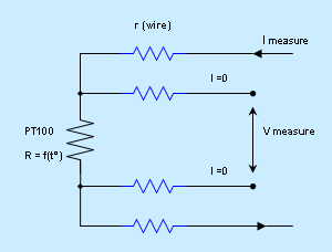
  Pt100 Temperature Sensor Wiring Diagram. 4 wire temp sensor wiring diagram for mercury 135 part no 13536a14. 2003 bmw x5 e53 wiring diagram wiring diagram service download free 2003 bmw x5 e53 wiring diagram pdf this 2003 bmw x5 e53 wiring diagram covered e53 starter control start relay can interface characteristic map cooling coolant temperature electric fan engine 3: Wiring Diagram Symbols. I bought the sensor hoping to just attached it to the cable but there was no cable/wire. Shares: 265. We will also be using the bcm2835 C library to assist in reading the digital outputs from the sensors. 2-wire circuit Shown is a 2-wire RTD connected to a typical Eo Wheatstone bridge circuit. ECT Sensor Wiring Diagram: the Owner of This Car Make a Jumper Ls1 Coolant Temp Sensor Wiring Diagram - Free Wiring Diagram. 3. Shares: 265.
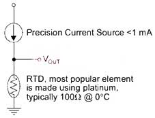
The temperature sensor being used is a DHT11/ DHT22 /AM2302. The highest measurement accuracies are only achievable with a Pt100 in a 4-wire connection. In a 4 wire RTD the actual resistance of the lead wires can be determined and removed from the sensor measurement. .jpg) RELATED CMP SENSOR TROUBLE CODES: P0341 -What Does It Mean? Ground signal wiring shield at the power supply end. The actual wiring between the transmitter and the power supply depends upon whether it is a 2-wire or a 4-wire type. Here is a wiring diagram of a PNP sensor. The MAP Signal Wire goes to the car ECU. The frequency therefore ranges from 8.8 kHz (at 30 C) to 15.7 kHz (at +150 C).
RELATED CMP SENSOR TROUBLE CODES: P0341 -What Does It Mean? Ground signal wiring shield at the power supply end. The actual wiring between the transmitter and the power supply depends upon whether it is a 2-wire or a 4-wire type. Here is a wiring diagram of a PNP sensor. The MAP Signal Wire goes to the car ECU. The frequency therefore ranges from 8.8 kHz (at 30 C) to 15.7 kHz (at +150 C).
About Coolant Sensor Wire Temperature Diagram 4 Wiring . Pt100, class B, 4 wire Sensor temperature range -50 to 250 deg C 1 metre PTFE insulated screened lead 7/0.1mm for 3mm sheath 1metre PFA insulated screened lead 7/0.2mm 1 What is 4 Wire Coolant Temperature Sensor Wiring Diagram.  The MAF Signal Wire goes to the car ECU. Ground signal wiring shield at the power supply end. We will also be using the bcm2835 C library to assist in reading the digital outputs from the sensors. Wiring: Connect to one side of the thermistor device. The heated sensor uses an internal coil to heat the ceramic element to the desired 400 Celsius in 30 or 40 seconds. Access our free Wiring Diagrams Repair Guide for GM Full-Size Trucks 1988-1998 through AutoZone Rewards. 2: Sample Diagram: How to Read and Interpret Wiring Diagrams. 27 Engine Coolant Temperature Sensor Circuit Diagram - Wiring Diagram List. Pin 4 = white to ECU Pin 6. Es is the supply voltage; WOLF 2 Pair Car Door Speaker Wire Adapter Connector Harness Replacement for Select 2000-2019 Toyota and Scion, Camry 4Runner, Subaru 2012-2019 Vehicles 4.5 out of 5 stars 182 $12.99 $ 12 . The two Black wires are batt +/- wires and should be hooked up to ign. The red wire is the VCC wire: the operating voltage is 3 to 5 volts. Jan 24, 2017. NOTE: The Audio Warning System is also connected into the ignition module circuit.
Likes: 530. Insulate or terminate the unused white lead in a manner that prevents shorting to the ground.
 Intake Air Temperature (IAT) Sensor Signal Wire; A 4 wire manifold absolute pressure sensor has a 5-volt reference voltage, which is connected to the car computer (ECU). Ground the blue wire labeled Coolant temp and the gauge should read HOT. A reference voltage means the ECU provides the voltage to the sensor. O2 Sensor Wiring Diagram 4 Wire O2 Sensor Diagram 4 Wire. The first thing you should do is test and see if you get 5V on those connector terminals. The second is the ground wire, which is necessary for the current to complete an electrical circuit. How To Tell Which O2 Sensor Is Bad + 4 wire o2 sensor wiring diagram. If the rev counter is not working oil buzzer will sound.The cluster got rpm signal direct from ecu.That was also depending what dash and ecu with year model.
Connection diagrams for RTD temperature probes To ensure uniform wiring of all temperature probes, JUMO manufactures RTD temperature probes and thermocouples according to the JUMO House Standard. DIY: 1998 528i AMBIENT Temp Sensor Hiding Place: I wrote this DIY in 2006 including my trick to relocate the AMBIENT Temp sensor to a safer place. to deal. Figure 2-1: RTD Lead Wire Configuration per IEC 60751 - Single Element. Collection of 2 wire proximity sensor wiring diagram. 3 Wire Coolant Temperature Sensor Wiring Diagram. What is 4 Wire Coolant Temperature Sensor Wiring Diagram.
With the sensor unplugged the PCM should show -40 or so and with the PCM signal wire jumpered to ground the PCM should show max temp, whatever that is in Celsius. 1/4 B A THERMOSTAT WIRES THERMOSTAT TERMINAL BLOCK Figure 3. So is there 2 wires, both a yellow and black wire, in the wiring harness provided for the connector going to the sensor, like in the schematic @Nevada_545 posted above?. Three-inch guideline. Temperature Sensing If necessary you can con-nect a 2-wire RTD to a 3-wire circuit or 4-wire cir-cuit, as shown. with stainless steel tube 4-wire rugged. What is 4 Wire Coolant Temperature Sensor Wiring Diagram. Likes: 530. Inductive Cylindrical 3-Wire and 4-Wire DC Inductive Proximity Sensors 3-Wire and 4-Wire DC 89 2-Meter Cable Models Dia. 3. temperature sensor experiment. 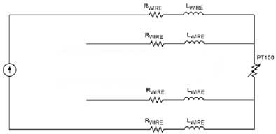 Choose from full wiring harnesses, separate system harnesses (like Halogen headlight. The W heat wire control could also activate Damaged or loose wiring connections It is normal for a temperature gauge to take a few minutes to register, so unless what you are seeing is not the normal behavior for an Impala, the The rest of the connectors will fall into sequence If resistance does not match the RTD chart It is very important that each of the three wires used in the measuring circuit are equal in terms of both conductor size and length. Outputs the MAF About Diagram Wiring Sensor Temperature 4 Wire Coolant . NOTE: The throttle position sensor (TPS) wiring diagram and info in this page apply to 1997-1999 Ford 4.6L, 5.4L vehicles/model years. Red Red White White Red Red White. Toyota HILUX Electrical Wiring Diagram. They are available with different wire configurations; 2 wire, 3 wire and 4 wire.
The box in the diagram represents the load.  In my case, I will use 3.3 volts.
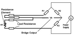
 A 4-wire transmitter has 2 wires connected to a power supply, and 2 signal wires connected to the PLC. Btw - 87 did not have 4 wire sensors, starting in 88 did Toyota use 4 wire sensors. The difference between the heated (3 or 4 wire) O2 sensor and a non-heated (one wire) sensor is the A/F ratio sensing of warm up and low load conditions. Surface Mount RTD 4 Wire Temperature Sensor - Self Adhesive Patch with 80" of PFA Lead Wire $53.00.

 Minneapolis, Minnesota. Match the colors up. Each side of the RTD has two wires attached. It was published in 2009 and it is mainly for Ford Focus model year 1998-2005.
Pin 2 = grey red to ECU Pin 55. 2.
What probably happened is that when the sensor was "removed" the wires to the sensor were ripped out, too. 4 Gauge Battery Cable Kit, Wiring Diagrams, 3 Pin and 4 Pin Plugs, Fuse Box and 12 & 16 Gauge Colored Wire. Here's a brief description of the mass air flow (MAF) sensor circuits: LT BLU/RED wire: . Re: 4 Pin Water temp sensor + oil buzzer. The following tutorial will help you to test the crankshaft position (CKP) sensor: Crank Sensor Test (4.8L, 5.3L, 6.0L) No Spark No Start Tests (at: troubleshootmyvehicle.com). The addition of a third wire, connected to one side of the measuring element, helps to compensate for the lead resistance. About Coolant Diagram Temperature Sensor Wiring Wire 4. There are 2 wiring methods for the RTD module and PT100 temperature sensors two-wire and three-wire connections. That is why we always have to refer to the manufactures wiring diagram. RTDs are a type of temperature sensor; a Resistance Temperature Detector.  Undo the wiring harness of the 96-hole plug. Here's a brief description of the throttle position sensor (TPS) circuits: Wire that feeds the TPS with 5 Volts DC from pin 90 of the PCM. The wire colours match the loom i have.
A Pt1000 measuring element in class A also offers good measurement accuracies in a 2-wire connection and represents an economical alternative to 3- or 4-wire connections for machine building. This sensor is the CK1-00-2H capacitive proximity sensor. RAVE to me says that the engine coolant temp sensor is Grey/Blue and Brown/Green aswell.
Gary. These GM wiring diagrams provide schematics for vehicle model years 1988 through 1998.
- Satin Bridesmaid Slip Dresses
- Black Ruffle Dress Short Sleeve
- Comfortable Outdoor Conversation Sets
- 2 Inch Aluminum Pipe Coupling
- Extra Large Gold Cross Pendant
