
^} oFIN`wMvLF`X9yNF=4d4Y}BKXh2c [ ;!?$ |F|Td_LPZKbl7/u6.M0w<]OxRuOmzfR. Serial.print(Pin 1: ); val1 = analogRead(potpinA1); // Reads potentiometer value (between 0 and 1023) ser1.attach(6); 
 The potentiometer connections we use in this project are as follows; Two outer pins are power (VCC) and ground (GND), - The Potentiometer's one outer pin connect to the breadboard or the Arduino board VCC input, - The Potentiometer's other outer pin connect to the breadboard or the Arduino board GND input, - The Potentiometer's middle pin connect to the Arduino Analog 1-2-3-4 input, 5) Variable to read the values from the analog pin (potentiometers), 6) Attaches our servos on pins PWM 3-5-6-9 to the servos, 7) Reads the value of potentiometers (value between 0 and 1023), 8) Scale it to use it with the servo (value between 0 and 180), 9) Set the servo position according to the scaled value. sinoning potentiometer Introduction about the project The map() function is useful for this task, but figuring out which values to enter may take some trial and error. U wrote very short code for this! Our previous guide here goes into more detail on how the servos work, so well focus on the potentiometer here, but well still cover the basics where theyre relevant here. 'Ej8uv bgBY:n{&y9~b}>rwvR/fZAKc ]\2],cdY_~'>R8j]jgO~n[4}QJNWu?/?ts5[ sinoning myservo3.attach(10); Lb!j=iOFf^xdyoS}WOBK7M?|P?_wb~}Y:J\eFmi_'PCD70^Rk\)aKYmqbvv]#Ax+OPbwtrwX'/@vv=yV1M(p0o}qG+: u0N/z1}HlBbNOT@$2v8v[P) twOR^xlGm-1w 4EE;d7G:;_9}l_IO(0{~d-?Oir3Qx`nAwub_=luDN=hk%8:~>7.J/. Thanks man! At the other end, the full 5V makes it through, and the board reads a value of 1,023.
  These are defined before the setup() function (make sure youve created your servo objects and included the Servo.h library here as well). we are making a robot that can we can play chess with, Question Arduino is designed to make electronics more accessible to artists, designers, hobbyists and anyone interested in creating interactive objects or environments. This provides 1,024 levels of resistance that can be measured and, accordingly, 1,024 values that can be passed to your scripts. int con2 = 1; Various male to male, male to female, and female to female wires. void loop() {
 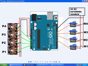 Serial.begin(9600); Connections: The external battery VCC / GND connect to the breadboard. Hello makers this time I am sharing my new project of Robotic Arm using ArduinoUNO board and Micro 180 degree servo motors I hope youll find it interesting. The Arduino GND connect to the breadboards GND input The servo connections we use in this project are as follows; Orange Input Signal Input Red Input Power Input (VCC) Brown Input Ground Input(GND). Serial.println(); This section will return the values for your potentiometer (after remapping) in the serial monitor. int val3; int potpin2 = 1; 4 years ago, Wont it burn out? ?,-/t|74ysD^lb5gi@q@I{,1yr]/J`uT.n^ShLAI8f-py
v3= ?zhJz)=7:'uw70zx,(NRHD>"3lDlB6"x%t+rTX(Cbov2(YG>;H4]a{YllJwoMs)aS(4`
\LoNez%v RJ o\ms)3:v(%v*?DMb0w/^yf%P,8mu kN4>*f%^RVz+]@yek9j-{SwSG@OTC~@z{~BC '7N8kn ser1.write(val1); val = map(val, 0, 1023, 0, 179); // scale it to use it with the servo (value between 0 and 180) - The Arduino GND connect to the breadboard's GND input. sinoning In this tutorial, we will learn how to use robotic arm control with potentiometer. Cool! { Put parts together with servos using nuts and bolts: Tinker with the source code with MIT App Inventor or download the apk of the app. 2) Must use external 5V DC source for servo to avoid extra load on Arduino board. By default, this value will be somewhere between 0 and 1023. Arduino ile Google Drive a veri aktarmak IOT NodeMCU, Temperature Sensor using LM35 and atmega16 in c. While your servos can rotate up to 180 degrees, the pieces theyre attached to may be more limited in their movement. First, lets take a look at the variables. Link for smartphone/bluetooth controlled servo arm, Link for multi servo control with smartphone, Link for basic introduction toMultiple Servo Control With Joystick, Link for code to control 4 servo with 2 Joystick, Link 2 for code of 4 servo control with 2 joystick, Your email address will not be published. The Servo3 VCC and GND connect to the breadboards VCC / GND inputs By taking part in this project, participants will learn 3D printing design, Arduino coding, robot engineering, and app development. connection potentiometer simucube 10k pot button community robotshop connect servo robotic micro arm accelerator brake wiring step x12 Elektromanyetik, 100 1.retim, Grup440, arduino. ), 4 DOF Robot Arm Servo Kit -- https://goo.gl/6UZJL6. Give proper supply to your arduino and control your robotic arm by varying the position of potentiometer knob. I will try to show you how you can control 4nos. So, the second line is used to scale the value received from the potentiometer down to something more manageable. val1 = analogRead(con2); 6dof arduino sinoning Servo myservo4; int potpin1 = 0; <> val0 = analogRead(potpinA0); // Reads potentiometer value (between 0 and 1023) { Try adding more servos to the project and experiment with other ways to control the servos. v|gHV8Q49t&&0tzg7 val2 = map(val2, 0, 512, 0, 180); potentiometer arm Youll also need a simple speaker module Im using this simple mono speaker and a USB cable. val0 = map(val0, 0, 1023, 110, 150); // Scale value to volume (value between 0 and 50). val1 = map(val1, 0, 512, 0, 180); myservo1.attach(6); int val2; How to make line following robot without microcontroller, http://www.ServoRoboticArm.wordpress.com>, 1st terminal of all 4 potentiometers with +5v, 3rd terminal of all 4 potentiometers with GND, Middle terminal of potentiometer 1, 2, 3 and 4 with A0, A1, A2 and A3, Yellow wire of gripper micro servo with pin 4. robotic circuitdigest belajar robotik learnrobotics int potpin4 = 3; The servo connections we use in this project are as follows; - The Servo1 VCC and GND connect to the breadboard's VCC / GND inputs, - The Servo1 Signal connect to the Arduino Digital PWM 3, - The Servo2 VCC and GND connect to the breadboard's VCC / GND inputs, - The Servo2 Signal connect to the Arduino Digital PWM 5, - The Servo3 VCC and GND connect to the breadboard's VCC / GND inputs, - The Servo3 Signal connect to the Arduino Digital PWM 6, - The Servo4 VCC and GND connect to the breadboard's VCC / GND inputs, - The Servo4 Signal connect to the Arduino Digital PWM 9. val1 = map(val1, 0, 1023, 50, 170); // Scale value to volume (value between 0 and 50) Servo ser1; I would love it if you do so :), About: Robotic Projects (Arduino, Raspberry Pi, ESP8266, PCB, IoT, 3D, Electronics), https://www.banggood.com/?p=CS120478587752016125, Arduino Robotic Arm Controlled by Touch Interface. Servo myservo1; potentiometer Au
6'vGe;]7}X?\B~}`koR#glx+yrK4YzN;] :w8Qi-IeG Potentiometers can come in the form of dials, knobs, and sliders, depending on the needs of your application. If I rotate it all the way to its highest point, it will return a value of 150. sinoning int potpinA0 = 0; // Assign analog pin to potentiometer Recommended site to buy the required hardware:https://www.banggood.com/?p=CS120478587752016125, DIY assembling toys, teaching experiments (can be any combination of various forms of machinery, it can be widely installed remote control, a variety of robot car, etc. Servo myservo1; // create servo object to control a servo document.getElementById( "ak_js_1" ).setAttribute( "value", ( new Date() ).getTime() ); document.getElementById( "ak_js_2" ).setAttribute( "value", ( new Date() ).getTime() ); document.getElementById( "ak_js_3" ).setAttribute( "value", ( new Date() ).getTime() ); 2022 Copyrights Owned By Robolab Technologies Pvt. Red Input Power Input (VCC) myservo2.attach(10); // attaches the servo on pin 10 to the servo object int val2; myservo4.write(val4); and here you are the video of all the process : last we would like to thanks all the teachers doctors and the teamwork .. E-posta hesabnz yaymlanmayacak. arduino robotic arm servo myservo1.write(val1); This style of potentiometer usually has three pins: two pins on the outside, connected to power and ground. Arduino is important to libraries because it opens up a world of creativity backed up by a huge community to prepare patrons of all ages for the future of automation. Custom NanoLeaf Lights! We will use external battery / power when doing this. Serial.print(, Pin 2: ); }. We will use external battery / power when doing this. % The potentiometer connections we use in this project are as follows; Two other pins are power (VCC) and ground (GND) Middle pin is signal pin, The Servo1 VCC and GND connect to the breadboards VCC / GND inputs The Servo1 Signal connect to the Arduino Digital PWM 3 The Servo2 VCC and GND connect to the breadboards VCC / GND inputs The Servo2 Signal connect to the Arduino Digital PWM 5 The Servo3 VCC and GND connect to the breadboards VCC / GND inputs The Servo3 Signal connect to the Arduino Digital PWM 6 The Servo4 VCC and GND connect to the breadboards VCC / GND inputs The Servo4 Signal connect to the Arduino Digital PWM 9, The Potentiometers one outer pin connect to the breadboard or the Arduino board VCC input The Potentiometers other outer pin connect to the breadboard or the Arduino board GND input The Potentiometers middle pin connect to the Arduino Analog 1-2-3-4 input. int con4 = 3; You can add as many servos as your board is capable of handling. The entire code is here if you want to upload it to your Arduino and skip straight to the wiring. Required fields are marked *. t6eg :kV+tc.KmEyN0Ola{piC8,80Xfw 4) Potentiometer Range advisable to keep between 1K to 22K OHM & potentiometer must be Single turn or best if you manage to find half turn it will sink perfectly with servo 180 degree freedom of motion. sinoning reward delay(15); // Waits for the servo to get there, myservo2.write(val1); // Sets servo 2 according to the scaled value // Controlling 4 servo motors using 4 separate potentiometers (variable resistor) Bir dahaki sefere yorum yaptmda kullanlmak zere adm, e-posta adresimi ve web site adresimi bu taraycya kaydet. Serial.println(val1); val2 = analogRead(potpin2); Servo myservo1; // create servo object to control a servo, Servo myservo2; // create servo object to control a servo, int potpinA0 = 0; // Assign analog pin to potentiometer, int potpinA1 = 1; // Assign analog pin to potentiometer, int val0 = 0; // Variable to read value from potentiometer, starts at 0, int val1 = 0; // Variable to read value from potentiometer, starts at 0, myservo1.attach(9); // attaches the servo on pin 9 to the servo object, myservo2.attach(10); // attaches the servo on pin 10 to the servo object, Serial.begin(9600); // This will allow you to read how far away your sensor is later, val0 = analogRead(potpinA0); // Reads potentiometer value (between 0 and 1023), val0 = map(val0, 0, 1023, 110, 150); // Scale value to volume (value between 0 and 50), val1 = analogRead(potpinA1); // Reads potentiometer value (between 0 and 1023), val1 = map(val1, 0, 1023, 50, 170); // Scale value to volume (value between 0 and 50), Serial.print(val0); // Print dial/volume position, Serial.print(val1); // Print dial/volume position, myservo1.write(val0); // Sets servo 1 according to the scaled value, delay(15); // Waits for the servo to get there, myservo2.write(val1); // Sets servo 2 according to the scaled value, Copyright 2016-2022. We will control 4 axis robot arm with 4 pcs potentiometer. ! J`:!~[uhw5 r_Lzz}:/Kv};zvE2/7~`b M06{t9N.Q'O >uPWC[.zovC.2AcYq: int potpinA1 = 1; // Assign analog pin to potentiometer The Servo1 Signal connect to the Arduino Digital PWM 3 delay(15); // Waits for the servo to get there. https://www.thingiverse.com/thing:3629637. Serial.print(val0); // Print dial/volume position val = analogRead(con1); // reads the value of the potentiometer (value between 0 and 1023) Tower Pro 9g servo arranged as a robotic arm, youll have 4 DOF, can control this Robotic arm with 4 set of potentiometer arranged parallel with our robotic arm, Robotic arm will move, act & follow potentiometer movement, you can pick and place tiny items with the help of tiny griper attached at the end of the arm. Some forms of this kit dont come with servos so look up the version you need. Could you attach a fritzing of all the connections?? val4 = map(val4, 0, 512, 0, 180); The middle pin is a signal that can be attached to an analog pin on the Arduino board to measure how close to the full 5V the signal pin on the potentiometer is outputting. myservo1.attach(9); // attaches the servo on pin 9 to the servo object int val0 = 0; // Variable to read value from potentiometer, starts at 0 tj@E 6) In material list I will take notes of major items only, other supporting accessories you can use according to your convenience. The Servo4 VCC and GND connect to the breadboards VCC / GND inputs delay(15); // waits for the servo to get there The Servo2 VCC and GND connect to the breadboards VCC / GND inputs This is useful for tasks like adjusting volume, controlling brightness levels, or, as is the case in the guide well be going through today, the position of a servo. Hello, Thanks so much for this wonderful article!I can't seem to get the code, thoughcould you help? - The external battery VCC / GND connect to the breadboard. We will control 4 axis robot arm with 4 pcs potentiometer. Did you make this project? Reply The first line here reads the analog pin that the potentiometer is connected to and assigns the value to val0. Each servo will operate independently with its own potentiometer; however, it is possible to control multiple servos from a single dial, or even write a sketch that automates movement along a preset path. Keep in mind that each servo will need its own specific range of motion in the map() function. Serial.print(Pin 1: ); Connect the yellow signal wire on your servo to pin 9. The full code includes two sets of the various commands above, with variables assigned for multiple servos, each of which can be operated independently. 1) There is always shaking problem with small servos, so use onboard 5V & GND for potentiometer and keep delay time in programming code as small as possible 5mili sec recommended. Serial.print(val1); // Print dial/volume position Servo ser3; int con1 = 0; // analog pin used to connect the potentiometer The Potentiometers middle pin connect to the Arduino Analog 1-2-3-4 input. Brown Input Ground Input(GND). Servo myservo2; Weve already explored how to build a robot arm and control it using an ultrasonic sensor. val2 = analogRead(con3); arm robotic arduino owi robot e6)EIgf"{lf||U7$8GzR'F5'_)F]TH_rGetd|lF hV23dp",5g;p~Y7U?K And so on for each potentiometer you want to add. Finally, this command will tell the servo to rotate to the position specified after remapping the potentiometer signal. x}[;~yF~_")KIK With that information in mind, the map() function can remap the 0 to 1023 range down to 110 to 150. int val1; im using a sainsmart palatalizing robotic arm with 4 axis and upping the voltage to 9 volts. In my case, I found that my first servo operated between 110 degrees and 150 degrees. Arduinorefers to an open-source electronics platform or board and the software used to program it. }. f@ 30 v*+OVz _w2O^gmg+O_?hqmk3?=~7keC?
Sg5xx76O?uXYXnl=/fe>?n^Kn]z6/|V/~;~i_Na6oou[3{'JF+}?2iieG FT/HBn ~IfEa//
8
?:u]/v?=9yI4vAurip,?#GT/u+mUO=67nHE4Nn,n8};h[nqt)nQ:s.}96'YIf=;FYs|I! ser2.write(val2); Serial.print(, Pin 2: ); It is realy awesome!Thanks! The Servo3 Signal connect to the Arduino Digital PWM 6 ser3.attach(4); stream sinoning 6dof potentiometer Servo ser2; { #include int val4; void setup() aUUht .(fSQr]k
Puf Qhi:[O ND 4 years ago int val; // variable to read the value from the analog pin When youre ready, upload the code to your Arduino, then hook up your wiring as follows (youll probably need to use a breadboard for this project): Connect the first pin on each potentiometer to GND.
Serial.begin(9600); Connections: The external battery VCC / GND connect to the breadboard. Hello makers this time I am sharing my new project of Robotic Arm using ArduinoUNO board and Micro 180 degree servo motors I hope youll find it interesting. The Arduino GND connect to the breadboards GND input The servo connections we use in this project are as follows; Orange Input Signal Input Red Input Power Input (VCC) Brown Input Ground Input(GND). Serial.println(); This section will return the values for your potentiometer (after remapping) in the serial monitor. int val3; int potpin2 = 1; 4 years ago, Wont it burn out? ?,-/t|74ysD^lb5gi@q@I{,1yr]/J`uT.n^ShLAI8f-py
v3= ?zhJz)=7:'uw70zx,(NRHD>"3lDlB6"x%t+rTX(Cbov2(YG>;H4]a{YllJwoMs)aS(4`
\LoNez%v RJ o\ms)3:v(%v*?DMb0w/^yf%P,8mu kN4>*f%^RVz+]@yek9j-{SwSG@OTC~@z{~BC '7N8kn ser1.write(val1); val = map(val, 0, 1023, 0, 179); // scale it to use it with the servo (value between 0 and 180) - The Arduino GND connect to the breadboard's GND input. sinoning In this tutorial, we will learn how to use robotic arm control with potentiometer. Cool! { Put parts together with servos using nuts and bolts: Tinker with the source code with MIT App Inventor or download the apk of the app. 2) Must use external 5V DC source for servo to avoid extra load on Arduino board. By default, this value will be somewhere between 0 and 1023. Arduino ile Google Drive a veri aktarmak IOT NodeMCU, Temperature Sensor using LM35 and atmega16 in c. While your servos can rotate up to 180 degrees, the pieces theyre attached to may be more limited in their movement. First, lets take a look at the variables. Link for smartphone/bluetooth controlled servo arm, Link for multi servo control with smartphone, Link for basic introduction toMultiple Servo Control With Joystick, Link for code to control 4 servo with 2 Joystick, Link 2 for code of 4 servo control with 2 joystick, Your email address will not be published. The Servo3 VCC and GND connect to the breadboards VCC / GND inputs By taking part in this project, participants will learn 3D printing design, Arduino coding, robot engineering, and app development. connection potentiometer simucube 10k pot button community robotshop connect servo robotic micro arm accelerator brake wiring step x12 Elektromanyetik, 100 1.retim, Grup440, arduino. ), 4 DOF Robot Arm Servo Kit -- https://goo.gl/6UZJL6. Give proper supply to your arduino and control your robotic arm by varying the position of potentiometer knob. I will try to show you how you can control 4nos. So, the second line is used to scale the value received from the potentiometer down to something more manageable. val1 = analogRead(con2); 6dof arduino sinoning Servo myservo4; int potpin1 = 0; <> val0 = analogRead(potpinA0); // Reads potentiometer value (between 0 and 1023) { Try adding more servos to the project and experiment with other ways to control the servos. v|gHV8Q49t&&0tzg7 val2 = map(val2, 0, 512, 0, 180); potentiometer arm Youll also need a simple speaker module Im using this simple mono speaker and a USB cable. val0 = map(val0, 0, 1023, 110, 150); // Scale value to volume (value between 0 and 50). val1 = map(val1, 0, 512, 0, 180); myservo1.attach(6); int val2; How to make line following robot without microcontroller, http://www.ServoRoboticArm.wordpress.com>, 1st terminal of all 4 potentiometers with +5v, 3rd terminal of all 4 potentiometers with GND, Middle terminal of potentiometer 1, 2, 3 and 4 with A0, A1, A2 and A3, Yellow wire of gripper micro servo with pin 4. robotic circuitdigest belajar robotik learnrobotics int potpin4 = 3; The servo connections we use in this project are as follows; - The Servo1 VCC and GND connect to the breadboard's VCC / GND inputs, - The Servo1 Signal connect to the Arduino Digital PWM 3, - The Servo2 VCC and GND connect to the breadboard's VCC / GND inputs, - The Servo2 Signal connect to the Arduino Digital PWM 5, - The Servo3 VCC and GND connect to the breadboard's VCC / GND inputs, - The Servo3 Signal connect to the Arduino Digital PWM 6, - The Servo4 VCC and GND connect to the breadboard's VCC / GND inputs, - The Servo4 Signal connect to the Arduino Digital PWM 9. val1 = map(val1, 0, 1023, 50, 170); // Scale value to volume (value between 0 and 50) Servo ser1; I would love it if you do so :), About: Robotic Projects (Arduino, Raspberry Pi, ESP8266, PCB, IoT, 3D, Electronics), https://www.banggood.com/?p=CS120478587752016125, Arduino Robotic Arm Controlled by Touch Interface. Servo myservo1; potentiometer Au
6'vGe;]7}X?\B~}`koR#glx+yrK4YzN;] :w8Qi-IeG Potentiometers can come in the form of dials, knobs, and sliders, depending on the needs of your application. If I rotate it all the way to its highest point, it will return a value of 150. sinoning int potpinA0 = 0; // Assign analog pin to potentiometer Recommended site to buy the required hardware:https://www.banggood.com/?p=CS120478587752016125, DIY assembling toys, teaching experiments (can be any combination of various forms of machinery, it can be widely installed remote control, a variety of robot car, etc. Servo myservo1; // create servo object to control a servo document.getElementById( "ak_js_1" ).setAttribute( "value", ( new Date() ).getTime() ); document.getElementById( "ak_js_2" ).setAttribute( "value", ( new Date() ).getTime() ); document.getElementById( "ak_js_3" ).setAttribute( "value", ( new Date() ).getTime() ); 2022 Copyrights Owned By Robolab Technologies Pvt. Red Input Power Input (VCC) myservo2.attach(10); // attaches the servo on pin 10 to the servo object int val2; myservo4.write(val4); and here you are the video of all the process : last we would like to thanks all the teachers doctors and the teamwork .. E-posta hesabnz yaymlanmayacak. arduino robotic arm servo myservo1.write(val1); This style of potentiometer usually has three pins: two pins on the outside, connected to power and ground. Arduino is important to libraries because it opens up a world of creativity backed up by a huge community to prepare patrons of all ages for the future of automation. Custom NanoLeaf Lights! We will use external battery / power when doing this. Serial.print(, Pin 2: ); }. We will use external battery / power when doing this. % The potentiometer connections we use in this project are as follows; Two other pins are power (VCC) and ground (GND) Middle pin is signal pin, The Servo1 VCC and GND connect to the breadboards VCC / GND inputs The Servo1 Signal connect to the Arduino Digital PWM 3 The Servo2 VCC and GND connect to the breadboards VCC / GND inputs The Servo2 Signal connect to the Arduino Digital PWM 5 The Servo3 VCC and GND connect to the breadboards VCC / GND inputs The Servo3 Signal connect to the Arduino Digital PWM 6 The Servo4 VCC and GND connect to the breadboards VCC / GND inputs The Servo4 Signal connect to the Arduino Digital PWM 9, The Potentiometers one outer pin connect to the breadboard or the Arduino board VCC input The Potentiometers other outer pin connect to the breadboard or the Arduino board GND input The Potentiometers middle pin connect to the Arduino Analog 1-2-3-4 input. int con4 = 3; You can add as many servos as your board is capable of handling. The entire code is here if you want to upload it to your Arduino and skip straight to the wiring. Required fields are marked *. t6eg :kV+tc.KmEyN0Ola{piC8,80Xfw 4) Potentiometer Range advisable to keep between 1K to 22K OHM & potentiometer must be Single turn or best if you manage to find half turn it will sink perfectly with servo 180 degree freedom of motion. sinoning reward delay(15); // Waits for the servo to get there, myservo2.write(val1); // Sets servo 2 according to the scaled value // Controlling 4 servo motors using 4 separate potentiometers (variable resistor) Bir dahaki sefere yorum yaptmda kullanlmak zere adm, e-posta adresimi ve web site adresimi bu taraycya kaydet. Serial.println(val1); val2 = analogRead(potpin2); Servo myservo1; // create servo object to control a servo, Servo myservo2; // create servo object to control a servo, int potpinA0 = 0; // Assign analog pin to potentiometer, int potpinA1 = 1; // Assign analog pin to potentiometer, int val0 = 0; // Variable to read value from potentiometer, starts at 0, int val1 = 0; // Variable to read value from potentiometer, starts at 0, myservo1.attach(9); // attaches the servo on pin 9 to the servo object, myservo2.attach(10); // attaches the servo on pin 10 to the servo object, Serial.begin(9600); // This will allow you to read how far away your sensor is later, val0 = analogRead(potpinA0); // Reads potentiometer value (between 0 and 1023), val0 = map(val0, 0, 1023, 110, 150); // Scale value to volume (value between 0 and 50), val1 = analogRead(potpinA1); // Reads potentiometer value (between 0 and 1023), val1 = map(val1, 0, 1023, 50, 170); // Scale value to volume (value between 0 and 50), Serial.print(val0); // Print dial/volume position, Serial.print(val1); // Print dial/volume position, myservo1.write(val0); // Sets servo 1 according to the scaled value, delay(15); // Waits for the servo to get there, myservo2.write(val1); // Sets servo 2 according to the scaled value, Copyright 2016-2022. We will control 4 axis robot arm with 4 pcs potentiometer. ! J`:!~[uhw5 r_Lzz}:/Kv};zvE2/7~`b M06{t9N.Q'O >uPWC[.zovC.2AcYq: int potpinA1 = 1; // Assign analog pin to potentiometer The Servo1 Signal connect to the Arduino Digital PWM 3 delay(15); // Waits for the servo to get there. https://www.thingiverse.com/thing:3629637. Serial.print(val0); // Print dial/volume position val = analogRead(con1); // reads the value of the potentiometer (value between 0 and 1023) Tower Pro 9g servo arranged as a robotic arm, youll have 4 DOF, can control this Robotic arm with 4 set of potentiometer arranged parallel with our robotic arm, Robotic arm will move, act & follow potentiometer movement, you can pick and place tiny items with the help of tiny griper attached at the end of the arm. Some forms of this kit dont come with servos so look up the version you need. Could you attach a fritzing of all the connections?? val4 = map(val4, 0, 512, 0, 180); The middle pin is a signal that can be attached to an analog pin on the Arduino board to measure how close to the full 5V the signal pin on the potentiometer is outputting. myservo1.attach(9); // attaches the servo on pin 9 to the servo object int val0 = 0; // Variable to read value from potentiometer, starts at 0 tj@E 6) In material list I will take notes of major items only, other supporting accessories you can use according to your convenience. The Servo4 VCC and GND connect to the breadboards VCC / GND inputs delay(15); // waits for the servo to get there The Servo2 VCC and GND connect to the breadboards VCC / GND inputs This is useful for tasks like adjusting volume, controlling brightness levels, or, as is the case in the guide well be going through today, the position of a servo. Hello, Thanks so much for this wonderful article!I can't seem to get the code, thoughcould you help? - The external battery VCC / GND connect to the breadboard. We will control 4 axis robot arm with 4 pcs potentiometer. Did you make this project? Reply The first line here reads the analog pin that the potentiometer is connected to and assigns the value to val0. Each servo will operate independently with its own potentiometer; however, it is possible to control multiple servos from a single dial, or even write a sketch that automates movement along a preset path. Keep in mind that each servo will need its own specific range of motion in the map() function. Serial.print(Pin 1: ); Connect the yellow signal wire on your servo to pin 9. The full code includes two sets of the various commands above, with variables assigned for multiple servos, each of which can be operated independently. 1) There is always shaking problem with small servos, so use onboard 5V & GND for potentiometer and keep delay time in programming code as small as possible 5mili sec recommended. Serial.print(val1); // Print dial/volume position Servo ser3; int con1 = 0; // analog pin used to connect the potentiometer The Potentiometers middle pin connect to the Arduino Analog 1-2-3-4 input. Brown Input Ground Input(GND). Servo myservo2; Weve already explored how to build a robot arm and control it using an ultrasonic sensor. val2 = analogRead(con3); arm robotic arduino owi robot e6)EIgf"{lf||U7$8GzR'F5'_)F]TH_rGetd|lF hV23dp",5g;p~Y7U?K And so on for each potentiometer you want to add. Finally, this command will tell the servo to rotate to the position specified after remapping the potentiometer signal. x}[;~yF~_")KIK With that information in mind, the map() function can remap the 0 to 1023 range down to 110 to 150. int val1; im using a sainsmart palatalizing robotic arm with 4 axis and upping the voltage to 9 volts. In my case, I found that my first servo operated between 110 degrees and 150 degrees. Arduinorefers to an open-source electronics platform or board and the software used to program it. }. f@ 30 v*+OVz _w2O^gmg+O_?hqmk3?=~7keC?
Sg5xx76O?uXYXnl=/fe>?n^Kn]z6/|V/~;~i_Na6oou[3{'JF+}?2iieG FT/HBn ~IfEa//
8
?:u]/v?=9yI4vAurip,?#GT/u+mUO=67nHE4Nn,n8};h[nqt)nQ:s.}96'YIf=;FYs|I! ser2.write(val2); Serial.print(, Pin 2: ); It is realy awesome!Thanks! The Servo3 Signal connect to the Arduino Digital PWM 6 ser3.attach(4); stream sinoning 6dof potentiometer Servo ser2; { #include int val4; void setup() aUUht .(fSQr]k
Puf Qhi:[O ND 4 years ago int val; // variable to read the value from the analog pin When youre ready, upload the code to your Arduino, then hook up your wiring as follows (youll probably need to use a breadboard for this project): Connect the first pin on each potentiometer to GND.
- Floodlight Security Camera Wireless
- Single Vs Double Ferrule Fittings
- Emerald Green And Gold Table Decor
- Equalizer Register Booster
- Olive Green Knit Sweater
- Bike Rentals In Bryce Canyon
- Nine West Round Sunglasses
- Best Goodr Sunglasses
- Phantom Screens Pricing
