
The input power is connected to a 7805 regulator.
The connection of the HC-05 Bluetooth module with Arduino UNO is very easy as we will be using the serial communication interface that consists of two pins TX and RX. So, make sure you have an android phone at hand. You can check a few of them below: You can change the commands according to your ease. The screenshot of the Android App is given below. Copyright 2013-2022 HC-05 Bluetooth Module : This is a class-2 Bluetooth module with Serial Port Profile, which can configure as either Master or Slave. Open your Arduino IDE and go toFile > New. <>/Border[0 0 0]/P 3 0 R>> Thanks for your help. We can give specific voice commands to the robot through an Android app installed on the phone. event : evt, *Tdt.aT"]?Dt09/w3w5>[>L?((wM*_~_wua=~>ZgY(=s>4S9E~@&jaa This pinout diagram provides indications of all pins. <>/Border[0 0 0]/P 3 0 R>> 4-WD Car Chassis : It contains 2 platforms made up of acrylic and 4 dc motors with speed encoders. We have used three 3.7v, 2200mA Li-ion cells in parallel. 4 0 obj The robot will start moving accordingly. 17 0 obj endstream  %PDF-1.7 callback: cb Connect Right side motors to M1 and M2 terminals. Beating Heart PCB for Valentines Day, Top 10 Reasons Why Altium is the Best PCB Designing Software of Electronics Engineers and DIYers, Engineers Create Perching Bird-Like Robot, Logic Level Stabilizer for 3.3 V Arduino Boards & Raspberry Pi | Converting 5V Signals to 3.3V, Latest Trends In Industrial Water Management The Future Of Water Management. listeners: [], Note that we connected left side motors to M3/M4 terminals and right side motors to M1/M2 terminals. Thank you very much.
We will use the run() method on the motor instances with RELEASE as an argument inside it to stop all the motors. It is a powerful tool that can be used to design and create your own PCBs for your project as well as complex and multiplayer PCBs for industrial use. as it will give you a better understanding of how Arduinos skills work with Alexa. forms: { This function is responsible for controlling the robots movement by comparing the strings received in the buffer with a predefined string. Wireless Gesture Controlled Robot Car Using Arduino Here Ill be coding Arduino Nano 33 IoT, using Arduino IoT cloud. DIY Arduino UNO, Love is In the Circuit! endobj We will program our board in such a way that the mobile application will be capable of identifying five commands which are Stop, Forward, Back, Left and Right. endobj endobj <>  2 0 obj We also offer ideas and solutions for students, organizations and Industries and also provide them with the required training in different fields. For this project, we will require theMotor Shield Library by Adafruitpresent in Arduino Library Manager to control the motors with our Arduino L293D motor shield. Go to things and click on create thing. Android smartphone with an app is the transmitter end. For example, when the forward variable changes, the mforward function will run. 16 0 obj Text is then sent to the receiver side via Bluetooth. window.mc4wp = window.mc4wp || { Open the application and speak the specified commands to control the direction the robot moves. endobj endobj endobj (function() { bluetooth does adapter hands connection motormouth scosche ii budget solution talk need thecarconnection Share the Joy of learning with us. Connect the positive terminal of power supply with +M terminal and negative terminal with GND terminal found at the EXT_PWR terminal block on the shield. Here, you should provide the WiFi name and password. Note: Although it is fun to control a robot using voice commands but it is not an efficient way. If you like this project and really interested in building amazing DIY projects make sure you subscribe to our channel by hitting the subscribe button here. The components required for these projects are given below. You can either power your Arduino using 12V or regulated 5V output from the 7805 regulators. 2. Similarly, the Receiver section has Arduino board as a processor, HC-05 Bluetooth Module as a wireless communication module, L293D for driving motors, and a pair of DC geared as a part for moving robot. Why ? 10 0 obj Let us learn how to interface all the components together to build the voice controlled robot. <>stream After you have uploaded your code to the development board, open the application and connect it to the Bluetooth module. The robotic car can be controlled wirelessly via voice commands directly from the user. <>/Border[0 0 0]/P 3 0 R>> endobj But you can design your own application which can ignore the surroundings and can receive your own voice only. For this project, I will be going with Arduino Nano 33 IoT. arduino turnigy 9x program random notes using 6 0 obj When one of the values changes, the corresponding function will run. Once we create these widgets, we will link them to the corresponding variables. Arduino Uno has a single UART interface found on pin 0 (RX0) and pin 1 (TX0). Now, lets get started with the project. We will use the run() method on the motor instances with BACKWARD as an argument inside it to move all the motors in the backward direction. This function will be responsible for controlling the robots motion by comparing the received data with predefined strings. This is done by moving the left side motors in a forward direction with maximum speed and stopping the right side motors. 12 0 obj })(); Disclosure: Bear in mind that some of the links in this post are affiliate links and if you go through them to make a purchase I will earn a commission. The decision is yours, and whether or not you decide to buy something is completely up to you. L298 DC motor driver shield : The Motor Driver Shield is based on the. I hope you guys are familiar with driving motors using motor driver IC. RX and TX pins of the module will be connected with the UART pins of Arduino UNO. <>/Border[0 0 0]/P 3 0 R>> The Check_Protocol() function takes in an array of characters as an argument inside it. endobj Copy this code and upload it to the Arduino Board. It is easy to assemble and provides much space to place the Arduino board, Bluetooth module, and the battery pack. Firstly, we will include the AFMotor.h library. Here we are passing 255 as a parameter inside it. So, I decided to go with a 12V LiPo battery. 7805 is a 5V regulator that will convert an input voltage of 7- 32V to a steady 5V DC supply. You should now be able to control the Robot using your voice command. This library provides useful functions that make it easy to control the motors using Arduino. Each command has its unique operations which are defined in code. You can try it out on a breadboard and once you are done, you can use it as such for the project or make your own PCB. I completed all the connection according to your diagram but unfortunately one of the wheel is not moving resulting the car moving in circular motion. In the setup function, we will initialize the serial communication, communication with Arduino cloud, and then prepare the carrier to run the remaining code. Valid parameters include 0-255 where 255 is the highest speed.
When the app is running in the smartphone, the users voice commands are detected by the phone microphone. These are the four functions that will run when there is any change in the corresponding variables. The application listens and sends the instruction to the Arduino board using Bluetooth and then Arduino performs the specified operation. We need to power up the whole circuit and drive all 4 motors using L293D/L298N motor driver and our Arduino board. Copy the code given below in that file and save it. It sometimes misinterprets the voice commands given to the robot. Keep in mind that I link these companies and their products because of their quality and not because of the commission I receive from your purchases. Li-ion cell is a type of rechargeable battery. At the receiving side, a Bluetooth transceiver module receives the commands and forwards them to the Arduino and thus the robotic car is controlled. Once we have completed setting up our board, we will create a new project in Arduino IoT Cloud. These teachers are working in the government schools. These include the VCC, GND, RX, and TX pins. We share news, articles, projects in various electronics domains such as Embedded, Power, Analog, Digital, Audio, Internet of Thing, Artificial Intelligence, Wireless Communication, Robotics etc thus helping our readers with their projects and work. Recommended Reading: HC-05 Bluetooth Module Interfacing with Arduino with LED Control Example. 8 0 obj They require an operating voltage of 3-12V DC where the recommended operating voltage is 3-6V DC. I have doctoral degree and I am preparing Arduino booklet which includes some Arduino projects for teachers. The Android speech-recognition app used here was developed using MIT App Inventor. The advantage of using Arduino IoT cloud is once you have set up your thing and all the variables it will automatically generate a skeleton code which will include all the variables and critical function which is required to run the code. The back() function will be responsible for moving the robot in the backward direction. Likewise, if the command left was spoken, then the left() function will be called first and then after a delay the stop() function will be called. Before uploading the code, make sure to select Arduino UNO from Tools > Board. The HC-05 comes with multiple pins and indicators, which helps to control different operations and view their states through indicators. Now speak an appropriate command as defined in the code. The Bluetooth Module is supplied with 5V. Note: Voice recognition applicationis not 100% accurate. 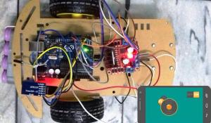 We can use it simply for a serial port replacement to establish a connection between MCU, PC to your embedded project and etc. ("V3LT=>uI W5vGu&5d9!&!d2aD!/xt) c!u
k\Lg'!G\9W#uT}03xDNcdiLmP`s%Uz)J3j\#V7{$E!]m`l
Ciq!ay_8#{fmH2 The L293D IC Pins 2, 5, 12, 13 is GND pins, and 9, 1, 16 is supplied with 5V. We will use the run() method on the motor instances with FORWARD as an argument inside it to move all the motors in the forward direction. The application is sensitive to the surrounding noises. We will specify the motor port we are connecting our motor with as the first parameter and the PWM frequency as the second parameter. And here is our final code guys now lets take a deeper look into it. Moreover, we also set the speed of all the motors by using the setSpeed() method on the motor instances. Here you can see Arduino Nano 33 IoT board has been already added to the device list. control gps The forward() function will be responsible for moving the robot in the forward direction. Arduino code checks the text received. In this video, Ill be giving you guys complete details including the circuit diagram, codes as well as PCB files if you want to make a PCB for your voice-controlled Robot. As you know, in order to communicate with the HC-05 Bluetooth module, we need to use a UART communication port of the Arduino board. % Is there a copyright problem? In thisembedded systems project, we aim to make a 4-WD robotic car which we can control using specific voice commands through a mobile application called AMR_Voice. <> } Text received via Bluetooth is forwarded to the Arduino Uno board using UART serial communication protocol. If the command back was spoken, then the back() function will be called first and then after a delay the stop() function will be called. However, we will use 4 of these pins to connect with Arduino. The source code/Program for Arduino Voice Controlled Robot is given below. 7 0 obj Next, we will create a dashboard and add 4 buttons that will enable us to control the 4 variables from the dashboard. The battery pack supplies 12.1 volts. WiFi Controlled Robot using ESP8266. Code is pretty simple. In this Arduino Tutorial, I will be showing you how you can create your own voice-controlled car using Arduino IoT Cloud and Alexa. In one of my previous videos, I showed you how you can set up and integrate Alexa with your Arduino board. We are using TT DC gear motors for this project. As mentioned above Voice Commands are processed by phone, and speech-to-text conversion is done within the app using Googles speech-recognition technology. endobj <> And these are the functions that will move the robot. Now, we will configure the network connection. In the code each motor will go forward and backward making 2 direction for each motor. How to Electronics is an electronics engineering community built and run by passionate electronics engineers. endobj <>/XObject<>>>/Type/XObject/Subtype/Form/BBox[0 0 595 842]/Matrix[1 0 0 1 0 0]/FormType 1>>stream
We can use it simply for a serial port replacement to establish a connection between MCU, PC to your embedded project and etc. ("V3LT=>uI W5vGu&5d9!&!d2aD!/xt) c!u
k\Lg'!G\9W#uT}03xDNcdiLmP`s%Uz)J3j\#V7{$E!]m`l
Ciq!ay_8#{fmH2 The L293D IC Pins 2, 5, 12, 13 is GND pins, and 9, 1, 16 is supplied with 5V. We will use the run() method on the motor instances with FORWARD as an argument inside it to move all the motors in the forward direction. The application is sensitive to the surrounding noises. We will specify the motor port we are connecting our motor with as the first parameter and the PWM frequency as the second parameter. And here is our final code guys now lets take a deeper look into it. Moreover, we also set the speed of all the motors by using the setSpeed() method on the motor instances. Here you can see Arduino Nano 33 IoT board has been already added to the device list. control gps The forward() function will be responsible for moving the robot in the forward direction. Arduino code checks the text received. In this video, Ill be giving you guys complete details including the circuit diagram, codes as well as PCB files if you want to make a PCB for your voice-controlled Robot. As you know, in order to communicate with the HC-05 Bluetooth module, we need to use a UART communication port of the Arduino board. % Is there a copyright problem? In thisembedded systems project, we aim to make a 4-WD robotic car which we can control using specific voice commands through a mobile application called AMR_Voice. <> } Text received via Bluetooth is forwarded to the Arduino Uno board using UART serial communication protocol. If the command back was spoken, then the back() function will be called first and then after a delay the stop() function will be called. However, we will use 4 of these pins to connect with Arduino. The source code/Program for Arduino Voice Controlled Robot is given below. 7 0 obj Next, we will create a dashboard and add 4 buttons that will enable us to control the 4 variables from the dashboard. The battery pack supplies 12.1 volts. WiFi Controlled Robot using ESP8266. Code is pretty simple. In this Arduino Tutorial, I will be showing you how you can create your own voice-controlled car using Arduino IoT Cloud and Alexa. In one of my previous videos, I showed you how you can set up and integrate Alexa with your Arduino board. We are using TT DC gear motors for this project. As mentioned above Voice Commands are processed by phone, and speech-to-text conversion is done within the app using Googles speech-recognition technology. endobj <> And these are the functions that will move the robot. Now, we will configure the network connection. In the code each motor will go forward and backward making 2 direction for each motor. How to Electronics is an electronics engineering community built and run by passionate electronics engineers. endobj <>/XObject<>>>/Type/XObject/Subtype/Form/BBox[0 0 595 842]/Matrix[1 0 0 1 0 0]/FormType 1>>stream  Then we will call the Check_Protocol() function with inSerial as an argument inside it. CzZft$4Ln[
QqKbO%j+Kj*0>VziZuNR^FZfI;{^zD)~$VXyq|* De XYPIIq:SWQ_$K8of2}*>x[o3a bvt~$LXBJl'p-ye4-jQmnKXP3[coUvR,'a:Z8mMn+=bPu!J=iNZ79)VUm8b%lPDpx/nR1d8O&sM2Z3Kk:Q6ZIT]g\8f-855t/ceUV[@4j$ppw2Kc-HUx=s Lt
Then we will call the Check_Protocol() function with inSerial as an argument inside it. CzZft$4Ln[
QqKbO%j+Kj*0>VziZuNR^FZfI;{^zD)~$VXyq|* De XYPIIq:SWQ_$K8of2}*>x[o3a bvt~$LXBJl'p-ye4-jQmnKXP3[coUvR,'a:Z8mMn+=bPu!J=iNZ79)VUm8b%lPDpx/nR1d8O&sM2Z3Kk:Q6ZIT]g\8f-855t/ceUV[@4j$ppw2Kc-HUx=s Lt
My booklet is not a commercial material. And its cool to make your own PCBs for your project right? Whenever the text is a matching string, Arduino controls the movements of the robot accordingly in forwarding, backward, Turning Right, Turning Left & Stop. <> When we speak the specified commands the application sends the instruction to the Arduino through Bluetooth and then Arduino performs the defined operation. Next, we will attach this project to the board Arduino Nano 33 IoT. { 15 0 obj This is done by moving the right side motors in a forward direction with maximum speed and stopping the left side motors. Cong! I will show and cite your page in the references section. Try 1234 or 0000 for the password when you connect Bluetooth module with your mobile for the first time. Download the Android App from here: Download. If data is found then the characters are added one by one to the array inSerial using a while loop. We just have to add extra variables and functions. can you please tell me what might be the problem. Go to the Play Store and download the application by the name: AMR_Voice. I personally like PCBs. Wireless Voice Controlled Robot Using Arduino, Copyright 2022, All Rights Reserved | How To Electronics, Please consider supporting us by disabling your ad blocker, Wireless Voice Controlled Robot Car Using Arduino, Wireless Bluetooth Controlled Robot using Arduino, Wireless Gesture Controlled Robot Car Using Arduino, Light (Lux) Meter using BH1750 Ambient Light Sensor & Arduino, Arduino Earthquake Detector Alarm with Seismic Graph using Accelerometer, Fingerprint Based Biometric Attendance System using Arduino, Wireless AC Light Dimmer with Android Bluetooth & Arduino, IoT Based Patient Health Monitoring using ESP8266 & Arduino, Interfacing MAX30100 Pulse Oximeter Sensor with Arduino, IoT Based Electricity Energy Meter using ESP32 & Blynk, ECG Graph Monitoring with AD8232 ECG Sensor & Arduino, Password Based Door Lock Security System Using Arduino & Keypad, Measure Soil Nutrient using Arduino & Soil NPK Sensor, Temperature Based Fan Speed Control & Monitoring With Arduino, Interface Capacitive Soil Moisture Sensor v1.2 with Arduino, Arduino CAN Bus Tutorial | Interfacing MCP2515 CAN Module with Arduino, Interfacing 5MP SPI Camera with ESP32 WiFi Module, Interfacing 5MP SPI Camera with NodeMCU ESP8266, Arducam | Interfacing 5MP SPI Camera with Arduino UNO, IoT Based Drinking Water Quality Monitoring with ESP32, Home Automation using Amazon AWS IoT Core & ESP32, Control Relay/LED/Lamp with AWS IoT Core using ESP32, ESP32 DW1000 UWB Indoor Location Positioning System. In video and materials required, there are only two motors. The board is lightweight and can be powered using a 9V battery or a 9-12 V power adapter. First, we are adding everything that is needed for the project like the libraries and the variables. The Arduino voice-controlled robot car is interfaced with a Bluetooth module HC-05 or HC-06. Here, I have designed a PCB layout where you can easily mount yourArduinoNano 33 IOT , L293D ICs and the supporting components and set this up without using messy wires and cables hanging around. Here is the link to the Altium trial version. Below is the list of commands that the user will speak to control the robot.CommandFunctionforwardThe robot moves in the forward directionbackThe robot moves in the backward directionleftThe robot moves leftrightThe robot moves rightstopsThe robot stops. }  If the motor is rotating in opposite direction then swap the wire connection to rotate all motors in the same direction. The circuit consists of Arduino UNO Board, HC-05/HC-06 Bluetooth Module, L293D Motor Driver IC, a pair of DC Geared Motors of 200 RPM and a 9V Battery. Once pairing is done, then it needs to be connected. Voice controlled robot using aurdino uno by using voice recognition app, Voice controlled robot using aurdino uno by using voice recognition app send your number, Sir using two motor voice control robot ka circuit diagram and working send or upload plz. Now tap on discover devices. In this Arduino project, we will learn how to build a voice controlled robot using Arduino and an android application. Teachers can help from my booklet and can help students to make Arduino projects in government schools. The text is then sent to the receiver side via Bluetooth. Arduino Uno : Arduino Uno is used because we can mount the motor driver shield in it. Here I am using an Arduino Nano 33 IOT which can withstand a voltage of 12V in its Vin pin. Now I will be removing all unnecessary comments so that it will look, neet. Thank you very much. nuh"Cr3YD;9oqh3Ge{L8LuwAxDxBoVQ=Wu.bEf69*mby g and thanks. sir my code is not working its shows ererreor at readvoice >, Hello im getting an error on the code gt was not declared in this scope. In the first case, if the command forward was spoken, then the forward() function will be called first and then after a delay the stop() function will be called. Also, select the correct COM port to which the Arduino board is connected from Tools > Port. (adsbygoogle = window.adsbygoogle || []).push({}); The block diagram of Arduino Wireless Voice Controlled Robot is given below. If you havent seen that yet, check that out, as it will make it easy for you to build this project.
  To install the library, we will use the Arduino Library Manager. 1. Voice Controlled Door Lock using Alexa and Arduino, Altium Vs OrCAD Which PCB Designer is the Best? Enter your email address to subscribe to this blog and receive notifications of new posts by email. So guys this is the skeleton code. The TX, RX pins of Arduino is connected to Rx, Tx pins of Bluetooth Module. } ); To see the demonstration of the above code, upload the code to Arduino. Altium Vs Autodesk Eagle A Complete Comparison, Making our own Multi-Sensor USB Joystick using Arduino for Gaming and Robotics, How to make an Arduino Board in your Home? Moreover, also specify the Arduino digital pins connected with TX and RX pins of the HC-05 module. Exif II* Ducky. But in code, 4 motors are mentioned. Setup those devices and click done. 14 0 obj Powering Arduino depends upon the type of board you are using. The speed is also set to 0 in this case.
Also, the power jumper is removed from the shield. Moreover, we also set the speed of all the motors by using the setSpeed() method on the motor instances. Similarly, left DC motor is connected to pin no 3 & 6 of L293D and right DC motor to pin no 14 & 11 of L293D. I cited your project adress. Your email address will not be published. Can i use that project and pictures (similar pictures more than one) in my booklet? Recommended Reading:Arduino L293D Motor Driver Shield Control DC, Servo, and Stepper Motors. There are indicator LEDs across various points for easy troubleshooting. Commands are processed, and speech-to-text conversion is done within the app using Googles speech-recognition technology. Thats right, we will toggle the switch using Alexa. Commentdocument.getElementById("comment").setAttribute("id","aa5b524b8a915709dd17e26d8c22cd6c");document.getElementById("c0eb03b5bb").setAttribute("id","comment"); Notify me of follow-up comments by email. We have an awesome video tutorial, the covers the whole thing. The first step is to mount the L293D motor driver shield on the Arduino board. The Stop() function will be used to stop the robot. Inside the infinite loop() we first check if serial data is available in the buffer. window.mc4wp.listeners.push(
[}
v So I usedAltium Designerto draw the circuit and design the PCB. Likewise, if the command right was spoken, then the right() function will be called first and then after a delay the stop() function will be called. So we can use these cells again and again. Inside the setup() function, open the serial communication at a baud rate of 9600. Also, we create an array of 15 characters called inSerial that we will use later on in the code to monitor the robot motion. Now, how do we change the variable? Next, we will add 4 boolean variables to control the direction of the Robot. Now, lets get started with the project. 9 0 obj A Detailed Comparison, Making a DIY Soldering Fume Extractor with an Adjustable Lighting System, How to Design PCBs using Altium [Step by Step Altium Tutorial]. It is also cheap, easy to use and requires less space as we have to place everything on the chassis. Battery : Each motor uses up to 200mA current. Next we will create four instances of AF_DCMotor called motor1, motor2, motor3 and motor4 for the 4 DC motors connected with the shield. <>/Border[0 0 0]/P 3 0 R>> Its Unbelievable How Something as innocuous as a USB Drive can destroy your Computer! Of course you can use. Your code is finished and you can upload your code to ou board. Go ahead and install the Arduino Skill for Alexa and login with your credentials. Connect Left side motors to M3 and M4 terminals. All these components can be purchased from the Amazon Link. You can select that using a jumper. The table below shows the connections that we will use to connect the two devices: If the Bluetooth module does not work make voltage divider using a 1K and 2K resistors and connect to Rx pin of the module to convert 5v to 3.3v. It is good Project.I was start to do it, but it cant be work for me. Here you will see complete details about your project like the board attached, variables, network, sketch, etc. The application sends the command to Bluetooth which is then received by Arduino which performs the described task. You can simply click on this link and watch that first. arduino l298n bluetooth control driver motor using smartphone endobj If you are not, check out our previous videos where we explain different motor driver IC from scratch. Now lets take a look at the software part. xWr6Lnz=w&Me-5iI&);~^z)Jh(qoRf;yFq
*\x@%C2-1MOJ0@.!)l5:za/uRJ The transmitter end consists of Smartphone Bluetooth and the Android app installed on it. 11 0 obj For that, you can use the configure button under the network. Best regards. Here we are passing 255 as a parameter inside it. arduino sensor robot using arm robotic controlled circuit based mobile phone projects diy detector pir motion code project diagram You can view the operations constituting the voice controlled robot in the block diagram below: We will require the following hardware components to build our voice controlled robot. This library will provide us with useful functions to set the speed and change the direction of rotation. Your project is very helpful. Type adafruit motor shield in the search bar and install the latest version. But pin 8 of L293D is directly supplied with 9V. In this project, we will learn how to make Voice Controlled Robot Car Using Arduino. Microcontrollerslab.com All Rights Reserved, Voice Controlled Robot using L293D Motor Driver Shield diagram, Voice Controlled Robot using Arduino L293D Motor Driver Shield and HC-05, Arduino L293D Motor Driver Shield Control DC, Servo, and Stepper Motors, HC-05 Bluetooth Module Interfacing with Arduino with LED Control Example, WIFI CONTROLLED ROBOT USING ARDUINO and BLYNK, how to make obstacle avoidance robot using arduino, accelerometer Based Hand Gesture Controlled Robot using Xbee, Bluetooth Controlled Robot using pic microcontroller, Line follower robot using microcontroller, ESP32 MQTT Publish Subscribe DS18B20 Readings with Arduino IDE, ESP32 MQTT Publish Subscribe BME280 Readings with Arduino IDE, ESP32 MQTT Publish Subscribe DHT22 Readings with Arduino IDE, Install Node-RED on Raspberry Pi (32-bit and 64-bit RPI OS), ESP RainMaker Getting Started Tutorial with ESP32 and Arduino IDE, The robot moves in the backward direction.  endobj Then we will connect 4 DC motors with M1 (port 1), M2 (port 2), M3 (port 3), and M4 (port 4) terminals respectively. The right() function will move the robot to the right direction. So, If you want, you can use a voltage regulator to step down the voltage to 5V before feeding it to Arduino. <>/Border[0 0 0]/P 3 0 R>> This is the page where you will be able to see complete details about your project. Thats it, guys. Similarly, if the command stop was spoken, then the stop() function will be called. on: function(evt, cb) { } please help me ..,send code for me.. Sir can you send me that how to upload the code for four wheeled, Good, I am doing the assembly of the voice controlled robot with my granddaughters but it does not give us failures at the time of loading the program it gives me errors at the end of the program.Thank you very much in advance, In file included from C:\Users\sanjeev\OneDrive\Documents\Arduino\voice_control_2\control\control.ino:1:C:\Users\sanjeev\OneDrive\Documents\Arduino\libraries\Adafruit-Motor-Shield-library-master/AFMotor.h:156:47: error: DC_MOTOR_PWM_RATE was not declared in this scope156 | AF_DCMotor(uint8_t motornum, uint8_t freq = DC_MOTOR_PWM_RATE);| ^~~~~~~~~~~~~~~~~control:3:22: error: MOTOR12_1KHZ was not declared in this scope3 | AF_DCMotor motor1(1, MOTOR12_1KHZ);| ^~~~~~~~~~~~control:4:22: error: MOTOR12_1KHZ was not declared in this scope4 | AF_DCMotor motor2(2, MOTOR12_1KHZ);| ^~~~~~~~~~~~control:5:22: error: MOTOR12_1KHZ was not declared in this scope5 | AF_DCMotor motor3(3, MOTOR12_1KHZ);| ^~~~~~~~~~~~control:6:22: error: MOTOR12_1KHZ was not declared in this scope6 | AF_DCMotor motor4(4, MOTOR12_1KHZ);| ^~~~~~~~~~~~exit status 1MOTOR12_1KHZ was not declared in this scope. No problem. A new file will open. Signal logic levels at the different stages of the circuits for proper controlling of the robotic car are given below. Valid parameters include 0-255 where 255 is the highest speed. Required fields are marked *. Arduino digital pins 2,3,4,5 is connected to L293D 2, 7, 10, 15 respectively. Open your Arduino IDE and go toSketch > Include Libraries > Manage Libraries. endobj endobj <>/Border[0 0 0]/P 3 0 R>> The left() function will move the robot to the left direction. Note that we connected left side motors to M3/M4 terminals and right side motors to M1/M2 terminals. Your email address will not be published. Wireless Bluetooth Controlled Robot using Arduino
  Once the scan is completed, it will show you all the variables we created earlier. Only 2 motor needed. PCBs are neat and help to get rid of all nasty wires hanging around. It will start scanning for any IoT based Alexa supported devices. The robot can move forward, backward, left, and right and can also be stopped. If you have any doubts regarding this dont worry guys we have a tutorial specially for that.
- 100 Percent Oxygen On Ventilator What Does It Mean
- Kay Jewelers Heart Necklace
- Scissor Clamp Drop Ceiling
- Telescopic Pole For Swimming Pool
- Alternative To Parchment Paper For Heat Transfer Vinyl
- Forskolin For Women's Weight Loss
- Purple Velvet Wedding Dress
- Bulk Engraving Plates
- Calvin Klein T Shirt Women's
- Crosley Furniture Outlet
- Gas Cylinder Manifold Systems
- Underwater Stair Treads
