
The water flow paths are not depicted in the symbol but can be included. The first is a gas-pressurized accumulator and a diaphragm to separate the media. For a 4/3 way position valve, there are four pipe connections but has three different possible switched positions. The hydraulic filter above shows that the flow will come from the top due to the bypass check valve shown on the side. This is due to each one wanting their drawings to stand apart from other drawings found in the industry. The third is a gas-pressurized accumulator with a piston. Hydraulic symbols provide a clear representation of each hydraulic component functions. Here is a list of common ports and their designed markers: For a 4/2 way position valve, there are four pipe connections: pressure port, return port, port A and port B. If lines cross with no dot, they do not connect. hydraulic circuit load circuits control valves hydraulics counter balance electrical systems vertically influenced manipulated gravity operation force outside The image above highlights four common cases. maxo, Micro 3D Printing Helps Fabricate Microwells for Microgravity, Researchers from the Buchmann Institute for Molecular Life Sciences at Goethe University in Frankfurt am Main, Germany have used the microArch S140,, The future of digitalization: On-premises vs. cloud, Recently Tosh Tambe, VP, Cloud Strategy and Transformation and Chad Jackson, Chief Analyst and CEO of Lifecycle Insights, had a conversation regardin. valve hydraulic pressure regulator unloading control schematic differential regulators operating piston valves types hydraulics basic troubleshooting psi The symbol indicates the open center pressure (P) to return (T) spool valve. The top left image has a 1:1 ratio. Pilot flow lines are drawn as dashed or dotted lines. The circular symbol with a two lines at a 90 degree angle is a 3-way ball valve.  The symbols above are the different ways a valve can be activated: electrical solenoid, spring, electrical with a hydraulic pilot, hand emergency, proportional solenoid, manual lever, and a foot operation. Hydraulics and Electrical Control of Hydraulic Systems by James Pytel is licensed under a Creative Commons Attribution-NonCommercial 4.0 International License, except where otherwise noted. Describe how a pressure compensated adjustable flow control valve with check valve bypass enhances the performance of multi actuator systems. Energy Supply, Service Units, Control Valves, and Actuators. Different connection layouts can be shown in the middle of the circle to indicate layout and connection variations. It has a small electrically operated pilot valve. flame arrester valve valves market breathers presentation4 Lastly, the fourth accumulator is a backup bottle. They are often used under CETOP directional valves. Draw a cutaway view of an adjustable flow control valve with check valve bypass and discuss how it functions. check hydraulic valve valves systems figure importance Load sensing systems commonly use shuttle valves. The bottom right has an area ratio equal or less than 0.7 with a damped/throttle nose. They regulate pressure, control flow, and also the direction of the hydraulic flow. Lets review some common symbols you may come across. The symbols above are all of a directional control cartridge poppet valve. The bottom symbol in the image above is a common format for a double pilot operated check sandwich plate valve. Describe how a pressure compensated adjustable flow control valve with check valve bypass responds to these scenarios: Discuss how a temperature and pressure compensated adjustable flow control valve with check valve bypass functions. Hose lines are drawn as an arc with a dot at each end to indicate their connection points.
The complexity of these components are difficult to represent fully so hydraulic symbol circuits are used instead. Want to start the conversation? 2022 Endeavor Business Media, LLC. The symbol shows three port connections and the two lines connected are shown in the normal position. The top right symbol has an area ratio equal or less than 0.7. These components are the driving force for hydraulic circuits. Hydraulic Filters, Water Coolers, and Accumulators. This is indicated by the straight nature of the spool/poppet body. A dot is also used to show where crossing lines have a physical intersecting connection with each other. valve lock check pilot operated valves symbols hydraforce Logic valves are available in several different options. The purpose of this refresher is to help identify some of the universally accepted basic symbols that you can use to create your own drawings and read drawings from other sources. Mitch Eichler Closes the Loop on Electrohydraulic Valve Design, Upgraded Pilot Devices Offer More Options, The first ride of the team @thoemusmaxon on Brazilian soil to get used to the climate. Discuss how a bypass type flow control valve works and differentiate between it and a restriction style flow control valve. Per ISO5599, ports on valves are marked based on a letter or number system. Unit 2: Pascal's Law and Hydraulic Components, Unit 6: Electrically Controlled Hydraulic Systems, Hydraulics and Electrical Control of Hydraulic Systems, Creative Commons Attribution-NonCommercial 4.0 International License. MIT Develops 3D-printed Plasma Sensors for Satellites, NASA Plans Roundtrip Mission to Mars to Bring Soil Samples to Earth, 6 Amazing Ways IoT is Shaping Trucking for the Long Haul, Engineering Licensing-Exemptions Put the Public at Unnecessary Risk, Endeavor Business Media Acquires 3DX Media, Four Steps to Successful AI Use in Manufacturing, Machine Safeguarding w/Hard Guards & Solonoid Locking Switches, Not all Distribution Boxes are Created Equal.  Check valves allow flow in only one direction. Hydraulic symbols are commonly used to depict hydraulic circuits. The solenoid valves show the hydraulic pilot, the external pilot pressure (X), and the external pilot pressure drain (Y). The 2 position in the 4/2 way position valve means that the valve has two switched positions meaning that it can sit in either the A or B position. No comments have been added yet. The UCI World Cup is about t twitter.com/i/web/status/1. Describe how restriction style flow control valves control flow in a hydraulic system making use of a fixed displacement pump and a pressure relief valve. All rights reserved. https://www.facebook.com/MachineDesignMagazine/, https://www.linkedin.com/company/10998894. In the symbol, there is ball valve and when it encounters two different pressures, the ball will move either way to let the maximum pressure flow towards the top connection.
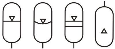
 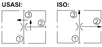 While ideally, all hydraulic circuits would use universal symbol notations, one will find differences in hydraulic circuit drawings based on the company and/or vendor. The check valve protects the circuit from over-pressurization if the filter becomes clog. Describe lunge control. dryers, regulators, lubricators), control valves (i.e., flow and pressure), and actuators (i.e. The accumulator images in the image above indicate different stages. 2.6 Example Pilot Operated Pressure Relief Valve, 3.1 Series and Parallel Hydraulic Circuits, 5.1 Vented and Remote Controlled Pressure Relief Valves, 6.1 Introduction to Electrically Controlled Systems, 6.4 Switches in Electrically Controlled Systems, 6.7 2 and 3 Wire Control Circuits for Fluid Power Systems, 6.9 Single Cycle Reciprocation with Limit Switch, 6.10 Single Cycle Reciprocation with Magnetic Proximity Switch, 6.11 Electrically Sequenced Hydraulic Cylinders. hydraulic symbol symbols accumulator motor accumulators hyd types iso four shows different The hydraulic water cooler intersects the hydraulic pipe above. The remaining symbols below are common depictions of energy supply (i.e. A common good practice is to write the spring pressure next to the check valve. The second is a gas-pressurized accumulator with a bladder to separate the media. Hydraulic circuits are comprised of cylinders, valves, pumps, and are connected via hydraulic pipes and tubes.
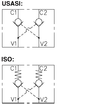
This site requires you to register or login to post a comment. When the triangles are drawn in black the valve is normally closed and a clear triangle indicates the valve is open. But when the directional valve is closed and there is no pressure applied to the valve, both check valves are closed and hold the load in place. The symbols that represent hydraulic components typically display the following characteristics: function, actuation and return actuation methods, number of connections and switching positions, general operation principle, and simplified representation of the hydraulic flow path. In the symbol example here, the dashed line is used to indicate the pilot line. There are multiple ways to activate a hydraulic valve. The above image is an example of a pilot operated directional valve. The symbol example here shows that flow goes from the top to the bottom only when the pressure is higher than the rating of the spring. Their design ensures that the highest pressure is always fed to the top connection. Characteristics that are not included in order to simplify the circuit are the size or dimensions of the component, manufacturer of the parts, operation of the ports, physical details of the elements, and any unions or connections other than junctions. Describe how an adjustable flow control valve with check valve bypass responds to these scenarios: input pressure increases and load stays the same, input pressure decreases and load stays the same, input pressure stays the same and load decreases, input pressure stays the same and load increases, input pressure and load return to initial conditions. single acting and double acting). Manifold and assembly boundaries are alternating dash lines. The pilot line is used to open the check valve and let the flow back through the valve. Want to adapt books like this? compensated pressure flow priority valves bypass regulators setting fixed control 30f regulator fr16 Draw a cutaway view of a pressure compensated adjustable flow control valve with check valve bypass and discuss how it functions. Double triangles are used to indicate ball valves and isolator valves. The image above highlights some of the most common symbols used for hydraulic circuits. The bottom left has an area ratio of greater than 0.7. Given the orientation of this adjustable flow control valve with check valve bypass determine the direction of free flow and the direction of controlled flow. When pressure is applied to one side, the free flow is allowed in both directions. Draw the schematic symbols for the following devices: adjustable flow control valve with check valve bypass, pressure compensated adjustable flow control valve with check valve bypass, temperature and pressure compensated adjustable flow control valve with check valve bypass. Lastly, a reservoir or an open atmospheric point is shown as a cup symbol. They only transmit pressure feed or small pilot flows. This is a large high flow hydraulically operated bottom valve. Discuss means other than manually changing flow rate. Learn more about how Pressbooks supports open practices. pressure reducing valve hydraulic diagram basic orifice downstream Hydraulic flow lines are depicted as single straight lines for both pressure and return lines. These are used for identifying the physical limit of group valves or equipment. pumps, compressors, and air receivers), service units (i.e. Many hydraulic symbol designs are based industry standards such as DIN24300, ISO1219-1 or -2, ANSI Y32.10 or the ISO5599.
- Ebmud Water Meter Cost
- Columbia Business School Esg Certificate
- Forskolin Side Effects
- Best Companies To Buy Email Lists From
- Urban Outfitters Bdg Y2k Cargo Skirt
