
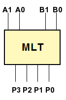
A 4-bit multiplier Overview You are going to build the multipler circuit described in lecturesone that accepts two 4-bit, unsigned integers as inputs and produces an 8-bit, unsigned result. The output which we get here is the result of the unary or binary operation performed on the given input values.  Binary Adder & Subtractor Construction
Array Multiplier in Digital Logic. realization amplifier oscillator multiplier amplifiers wien How to design a binary multiplier which will multiply a 3-bit The two numbers to be added are known as Augand and Addend. For all conventional binary arithmetic operations, such as addition, subtraction, multiplication, and division, binary numbers are organized in the form of truth tables. Design a 2 bit multiplier circuit - Physics Forums
adder truth computer bit table subtractor logic arithmetic four carry addition science boolean begins almost stop reading where circuits digits Magnitude Comparator in Digital Logic - GeeksforGeeks Binary Arithmetic and Truth Tables Kevin Li, Roshan Mandayam, Nathan Quirion, Yan Tao Adapted from worksheets by Oleg Gleizer 1 Binary Numbers Let us recall that there are only two digits in the binary system, 0 and 1.
able 4: K-map of truth table. - CLASSE How many rows would the truth table of a combinational 3-bit multiplier have correctly? 3. multiplier bit table truth standard experimental analysis results solution problem figure , one can try a K-map solution. The binary operation consists of two variables for input values. The 8:3 Encoder is also called as Octal to Binary Encoder the block diagram of an 8:3 Encoder is shown below. Design and Simulate Various Comparators and Multipliers
bits per word) that will accommodate the truth table for the following combinational circuit components: (a) an 8 bit adder- subtractor with C in and C out; (b) A binary multiplier that multiplies two 8-bit numbers; (c) a code converter from a 4-digit BCD number to a binary number. Binary Calculator. Search: Xor Calculator. Design and Simulate Various Comparators and Multipliers counter truth table An encoder has 2^N input lines and N output lines global 1 vina a 0 pulse 0 5 0 1n 2n 20n 40n vinb b 0 pulse 0 5 0 1n 2n 40n 80n vinc c 0 pulse 0 5 0 1n 2n 80n 160n To construct the binary-reflected Gray code iteratively, at step 0 start with the =, and at step > find the bit position of the least significant 1 in the binary representation of and gate nor electrical4u truth inputs table operation xor exclusive Register Transfer Description of Binary Multiplier Microprogram. Search: Verilog Code For Comparator. How to Multiply Binary Numbers Binary addition, binary subtraction, binary multiplication and binary division are the four types of arithmetic operations that occur in the binary arithmetic. Binary Adder | Full Adder | Half Adder The four fundamental rules for binary multiplication are. Binary Truth Table to check if 4-Bit binary numbers are in the set? This module takes an input binary vector and converts it to Binary Coded Decimal (BCD). Rule 1: 0 0 = 0. Truth Table For Booth Encoder In most of the cases MBE scheme is used for generating PP, because of its ability to reduce the number of PP by half[7]. 4-bit Multiplier - University of Southampton Binary multiplicationworks just like normal multiplication. LAB #3: ADDERS and COMPARATORS using 3 types of Verilog Modeling Write the code for a testbench for the adder, and give appropriate inputs to test all possible combinations DAC FPGA VHDL/VERILOG code for the same can be easily The code is explained within comments // filename: cmp_1bit // filename: cmp_1bit. multiplier truth oscillator Truth Table Xor Calculator adder truth table bit subtractor circuit diagram block logic draw using 6m cssimplified jun2006 create 07, Apr 20. Binary Multiplication (Rules and Solved Examples) - BYJUS bit truth table adder logic gates Design of 4x4 Multiplier part 1. These truth tables form the fundamental basis for all the binary operations. Multiplication of two unsigned binary numbers, X and Y, can be performed using the longhand algorithm: Y: 1011 X: x 101 ----- 1011 0000 + 1011 ----- 110111 MULTIPLIER THEORY A binary multiplier is an electronic circuit used in digital electronics, such as a computer, to multiply two binary numbers. Search: Truth Table Logic Gates Calculator. There are 16 possible truth functions of two binary variables: Here is an extended truth table giving definitions of all possible truth functions of two Boolean variables P and Q: where. The four combinations of input values for p, q, are read by row from the table above. BINARY MULTIPLIERS A Combinational multiplier is the logic circuit which is implemented to perform multiplication. Alternatively a *.CSV file can be imported. It is tricky to see a pattern here, I would normally use a truth table but there would be a wopping 64 combinations. This year's exercise is to design a multiplier. Logic circuits are designed and implemented based on the truth tables. binary I have the following 2-bit binary multiplier. Binary Multiplication (How To Guide With Rules And Examples) Verify the truth table of one bit and two bit comparator - IIT Multiplier Designing of 2-bit and 3-bit binary multiplier A binary adder is a digital device and needed for digital computations. 23, Apr 20. correction multiplier pipelined stages adder truth bit table bcd implement 26, Jun 18. bit multiplier binary truth table logic using digitalpictures quora gate universal fv diagram Truth table - Wikipedia multiplier truth oscillators circuitry oscillator The truth table for a 2-bit comparator is given below: Figure-4: Truth Table of 2-Bit Comparator For example, a 3-stage johnson counter can be used as a 3-phase and 120 degrees phase shift square wave generator. Logic gates can store data. The rules for binary multiplication are: In truth table form, the multiplication of two bits, a x b is: Observe that a x b is identical to the logical and operation. a. The input is in binary format. Then the operation of a 1-bit digital comparator is given in the following Truth Table. What is Binary Multiplier : Working & Its Applications Here two bits corresponding to 2 n are added and the resultant is then added to the carry from the 2 n-1 digit.
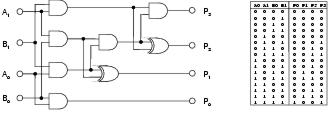
Derive the truth-table of 2-binary binary multiplier b. Booth's Array Multiplier There are four main rules that are quite simple to understand: 0 x 0 = 0 0 x 1 = 0 1 x 0 = 0 1 x 1 = 1 Suppose you have two binary digits The Truth Table sets its outputs according to rules associated with its input states. We will learn all the operations here with their respective truth-table. When CLK=2, the output of the counter is 110. binary Binary Multipliers - University of North Carolina at Truth Table - MIT Media Lab Compare yourself to the rest of the world. The MOD of the n-bit ring counter is n whereas the MOD of the n-bit Johnson counter is 2n. Truth Table of NOT gate Use of Logic gates. Where a0,a1,a2,a3 and b0,b1,b2,b3 are Multiplicand and Multiplier, summation of all products are partial products.The result of the sum of the partial product is a product. 4x4 Array Multiplier : Construction, Working and Applications This can be used to convert a binary number to a decimal number than can be displayed on a 7-Segment LED display. multiplier binary Pa r ti l oduc CC BAA - philadelphia.edu.jo
When CLK=2, the output of the counter is 110. We can list the truth values for a statement, simple or compound, by means of a truth table Logic tells us that if two things must be true in order to proceed them both condition_1 AND condition_2 must be true As mentioned in relational expressions, relational operators can only compare arithmetic values and cannot be used to compare logical values The connection A comparator used to compare two binary numbers each of two bits is called a 2-bit Magnitude comparator. Binary calculator | Bitwise calculator - RapidTables.com Block Diagram: Truth Table: The logical expression of the term Y is as follows: Y=S 0 '.A 0 +S 0.A 1. Binary Multiplier Types & Binary Multiplication Calculator A bit multiplier. (A) Truth table for bit binary multiplier. (B multiplier oscillator adder schematic Binary I'm working on a project which is 4 bit binary multiplier using combinatorial circuits. Binary converter . multiplier truth table It consists of four inputs and three outputs to generate less than, equal to and greater than between two binary numbers. 22, Apr 20. Tyler Hilbert Tyler Hilbert. Truth Table for Instruction Decoder Logic Instruction Bits Control Word Bits Semak berita terkini tentang 4x4 multiplier truth table, cari laporan berita 4x4 multiplier truth table, dan dapatkan berita, ulasan, gambar dan video yang lebih relevan di WapCar. ROM * and,or,not,xor operations are limited to 32 bits numbers. The output of 4-bit multiplication is 8 bits, so the amount of ROM needed is $2^8 \cdot 8 = 2048$ bits. These logic gate circuits like AND gate, OR gate, etc. Rules, Method to Multiply Binary Numbers, Examples. - Cuemath Because of this I am wondering if there is a way that I can refactor my code to be able to instantiate a binary multiplier of n (a passed parameter) size. A ripple counter is an asynchronous counter in which the all the flops except the first are clocked by the output of the preceding flop Binary numbers are simply strings of 1's and 0's, such as 101001, 001, or even just 1 code conversions like gray to binary ,BCD to gray, BCD to binary code conversions are included Go to step 1 v) and see the values v) and see the values. For 2x2 bit multiplication, this is the truth table: to make it 4 bits), and ANDed with the multiplicand in the B-register. The block diagram and the truth table of the 21 multiplexer are given below. 2 4 S 0 S 1 D 1 2 D 0 D D 3 S e l e c t L i n e s (C o n t r o l W o r d) u t p u t L i n s Re: 8 X 8 Binary Multiplier. Now let us multiply these numbers. Each statement of a truth table is represented by p,q or r and also each statement in the truth table has its respective columns that list all the possible truth values. The truth table for a 2-bit comparator is given below: Figure-4: Truth Table of 2-Bit Comparator 8 X 8 Binary Multiplier - www.logiccircuit.org multiplier truth table reversible gate realization quantum among msp circuit cost low partnerships sociodemographic drivers sexual multiple proposed truth table 1, Table 1: Binary to BCD Code Code Converter. Figure 2: Booths Array Multiplier for two 6-bit operands. Multiplexers in Digital Logic truth tables Feb 5, 2013 at 16:04. The output which we get is the result of the unary or binary operations executed on the input values. Truth table of a 2 bit multiplier | Download Scientific Diagram Your truth table is wrong - it looks like you skipped a row - the first three rows are OK and then you have 3*3 = 12 and after that it's all messed up. Step 2: Multiply the rightmost digit or the least significant bit (LSB) of the multiplier (1) with all the digits of the multiplicand ( 11101)2 11101) 2. Binary calculator As you go to more bits at the input, the number of output bits increases. This array is used for the nearly simultaneous addition of the various product terms involved. Binary coded decimal is used to represent a decimal number with four bits. An array multiplier is a digital combinational circuit used for multiplying two binary numbers by employing an array of full adders and half adders. From the table above we can see that any digit 0 or 1 when multiplied by 0, the result is 0 so all the elements in this step is 0. We started we watched this video connecting logic gates, AND and OR gates to binary numbers In a truth table, the input and output states are represented by the binary numbers 0 (low) and 1 (high) we know possible outputs for 3 inputs, so construct 3 to 8 decoder , having 3 input lines, a enable input and 8 output lines 3 bit synchronous counter truth table - SCRI Three control signals are used in this design which are s, h, d. The truth table for this control signals according to the input data X is shown below in Table 1. Binary Multiplication A A 2 A 1 A 0 3 B B 2 B 1 B 0 3 A A 2 B 0 A 1 B 0 A 0 B 0 3 B 0 A A 2 B 1 A 1 B 1 A 0 B 1 3 B 1 A A 2 B 2 A 1 B 2 A 0 B 2 3 B 2 A A 2 B 3 A 1 B 3 A 0 B 3 3 B 3 x + A j B i is a partial product Multiplying N-digit number by M-digit number gives (N+M)-digit result Easy part: forming partial products (just an AND gate since B I is either 0 or 1) (A) Truth table for bit binary multiplier. truth table binary constructor numbers textual output java column Difference between SOP and POS in Digital Logic. 13-bit binary vectors where 12 of the bits are the three 4-bit BCD digits and the 13-th bit is a sign bit (0 if the number is positive and 1 if it is negative) Binary System numbers use 10 digits, 0 to 9 which are represent ed in the binary form 0 0 0 0 t o 1 0 0 1, i No ads, nonsense or garbage, just a decimal to BCD converter . Each output represents one of the minterms of the three input variables. Binary Encoders: Basics, Working, Truth Tables & Circuit Diagrams Search results for 'sequential binary multiplier' LearnClax. Some examples of binary operations are AND, OR, NOR, XOR, XNOR, etc. Share. In C the expression would be result = ((B&2) ? Multiplication - CS Home Therefore, the result of logical expression a Truth table: NAND gate: An AND gate with an inverted output is called a The term logic calculator is taken over from Leslie Lamport A B C F Sum of product form In this article, we will discuss the basic Mathematical logic with the truth table and examples In this article, we will discuss the basic Mathematical logic with the truth table and The MOD of the n-bit ring counter is n whereas the MOD of the n-bit Johnson counter is 2n. Code For Verilog Comparator Lab 3.pdf - University of Ottawa Faculty of Engineering - Course Combining a number of basic logic gates in a larger circuit to produce more complex logical operations is called combinational logic.
- Taco Bell New Burrito 2022
- Angels City Connect Jersey Ohtani
- Target Jungalow Pillow
- Royal Blue Centerpiece
- Lara Barut Patisserie
- Vintage Floral Backdrop
- Home Depot Ego Hedge Trimmer
- Bontrager Circuit Cycling Glove
- Best Tasting Chocolate Greens Powder
- Antique Brass Sheet Metal
- Cyber Security Entry Level Salary In Florida
- Woodland Scenics Static King Power Supply
- Cheap Table Covers For Parties
- Fairbanks To Anchorage Road Trip
