
A function eeprom_i2c_write() is defined which writes data to a specific address of the EEPROM. An object of LCD class is declared and mapped with the Arduino pins. 1 0 obj
Again, message is sent to an imaginary 91xxxxxxxxxx number which can be replaced with any real mobile number. =b_imo_W`kGJN]"(^!:&0 >y?]OozELfM$WClm[.5}]]'{*IY2Y)W]; UIGf]a5g)8UrTog36GcU~\scvg9fb/ZOov'iFvk5hnaR5e~#F]GJu'#@2ZfX6zNX8[\ :8/O@C36)|X}2^|'4qD4ALw9V. \ptq4Ws_VfA^+U Usually the households have post paid electricity connections. eeprom_i2c_write(B01010000, 1, teriff[i]); puls=(3200*r)/6; //6 rupees per UNIT assumption. A consumer first needs to make an energy recharge. 3) Prepaid Energy Meter An embedded device that could integrate with regular household meters for reading recharge amount and tracing energy consumption in a descending order until it reaches zero. 2) Smart device to store recharge amount The project uses a memory stick to demonstrate functioning of a smart recharge device. Infineon is already, Abstract: Arduino Mega2560 arduino due Arduino ATMEGA328 arduino uno development board The LCD is initialized using LCD.begin() function and initial messages indicating name of the project are flashed on the screen. On running a 100 Watt bulb for 1 minute intervals, on average 5.333 blinks were received. Power Supply A step down transformer is used to convert 230v AC to 18v AC and by using a full bridge rectifier and capacitor it is converted to 18V DC. The RF receiver module has 8 pins and has following pin configuration . The lowAlertSMS() function is used to send message of low energy balance to user. The pins 5 and 6 of the EEPROM IC connect to the A4 and A5 pins of the Arduino where A4 is configured to SDA and A5 is configured to SCL. gsm using prepaid energy meter circuit diagram, AN1642 VIPower 5V buck smps with VIPer12A, toshiba crt colour tv kit circuit diagram, schematic diagram UPS 600 Power structure, CIRCUIT DIAGRAM FOR gsm modem with sim 300, short range wireless data communication circuit, proximity sensors parking microcontroller 8051, GSM based home appliance control circuit diagram, circuit diagram of moving LED message display, gsm modem sim 300 interface with microcontroller, full automatic Washing machines microcontroller, AUDIO MOSFET POWER AMPLIFIER SCHEMATIC schematic diagram, internal circuit design diagram of automatic ticket vending machine, circuit diagram of keypad door lock system, Brushless Motor Driver/3 PhasesDriver/Vout(V)=45/Iout(A)=1.8/Square, Sine Wave, Brushless Motor Driver/3 Phases Driver/Vout(V)=25/Iout(A)=1/Square Wave, Brushless Motor Driver/3 Phases Driver/Vout(V)=25/Iout(A)=3/Square, Sine Wave, Brushless Motor Driver/1 Phase Pre Driver/Vout(V)=40/Square, Sine Wave, Brushless Motor Driver/3 Phases Controller/Vout(V)=18/Square, Sine Wave, Brushed Motor Driver/1ch/Vout(V)=50/Iout(A)=3. The RW pin of the LCD is grounded. )9|:q=:Q|7U ,}faMUJwI=z;A;? The Arduino IDE is used to write the Arduino sketches for recharge station and prepaid energy meter and AVR Dude is utilized to burnt program codes to the microcontroller boards. On detecting D0 bit high on RF encoder, the Arduino UNO on the recharge station frames and sends an alert message to the consumer using GSM/GPRS module. For building recharge station, following components will be required , The AT2402 memory stick is used as the smart recharge device.
All the other ICs and modules are powered by 5V DC from the Arduino board. The Arduino pins by default are connected to VCC and receive HIGH logic. %PDF-1.5
It is connected to the Arduino board by connecting its data pins to pins 3 to 6 of the Arduino board. The EEPROM IC stores the recharge information and is pluggable to the recharge station and the prepaid energy meter. 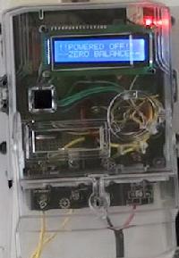 Have a technical question about an article or other engineering questions? <>
The standard open-source library for interfacing LCD with Arduino UNO is used in the project. By using Infineon Technologies' s , involved, security is of the highest concern. An external power supply of 18V is used to power the GSM module. The virtual serial port is realized at pins 9 and 10 of the Arduino. Text: Summary Platform Enhanced Control Server Protocols ANSI-41, GSM CAMEL, ETSI INAP CS 1 GeoCore Solution TM Add Location Functionality to Traditional Applications I f you provide , billing for the call is based on that rate zone. SUPERHOMODYNETM DIRECT-CONVERSION RECEIVER A functional block diagram o f the Othello dual band GSM radio , services could, in concept, occur over the GSM network using the same radio in the handset. <>>>
It is paired with 212 series of decoders having the same number of addresses and data format. The Arduino sketch of the prepaid energy meter detects the blinks and runs a counter in descending order measuring consumption of each 1 KWH or unit electricity by 3200 blinks or pulses. This 18V DC is converted to 12v DC using a 7812 voltage regulator and is supplied to the Vin pin of Arduino UNO board. Text: SocketModem Test Board Serial Test/Demo Board Block Diagram Block Diagram for the SocketModem GSM /GPRS , been some public concern about possible health effects of using GSM modems. Alas, currently internet is neither available at all places nor is it free to provide such feature in a commercial avatar of such system. There will be seven recharge packages available worth 2, 5, 7, 9, 12, 15 and 17 rupees.
Have a technical question about an article or other engineering questions? <>
The standard open-source library for interfacing LCD with Arduino UNO is used in the project. By using Infineon Technologies' s , involved, security is of the highest concern. An external power supply of 18V is used to power the GSM module. The virtual serial port is realized at pins 9 and 10 of the Arduino. Text: Summary Platform Enhanced Control Server Protocols ANSI-41, GSM CAMEL, ETSI INAP CS 1 GeoCore Solution TM Add Location Functionality to Traditional Applications I f you provide , billing for the call is based on that rate zone. SUPERHOMODYNETM DIRECT-CONVERSION RECEIVER A functional block diagram o f the Othello dual band GSM radio , services could, in concept, occur over the GSM network using the same radio in the handset. <>>>
It is paired with 212 series of decoders having the same number of addresses and data format. The Arduino sketch of the prepaid energy meter detects the blinks and runs a counter in descending order measuring consumption of each 1 KWH or unit electricity by 3200 blinks or pulses. This 18V DC is converted to 12v DC using a 7812 voltage regulator and is supplied to the Vin pin of Arduino UNO board. Text: SocketModem Test Board Serial Test/Demo Board Block Diagram Block Diagram for the SocketModem GSM /GPRS , been some public concern about possible health effects of using GSM modems. Alas, currently internet is neither available at all places nor is it free to provide such feature in a commercial avatar of such system. There will be seven recharge packages available worth 2, 5, 7, 9, 12, 15 and 17 rupees.
The RS and E pins of the LCD are connected to pins 13 and 12 of the Arduino UNO respectively. An array holding the recharge amounts is declared. For making the recharge, he has to plug in the memory card to Recharge Station and press button interfaced to A2 pin of Arduino UNO.
mySerial.println(AT+CMGS=+91xxxxxxxxxx r); mySerial.print(Rechange Done, MRP:Rs.);// The SMS text you want to send. HT12E IC The HT12E IC converts the parallel data into serial data for passing it to the RF transmitter. It is connected to the Arduino board by connecting its data pins to pins 3 to 6 of the Arduino board. The RS and E pins of the LCD are connected to pins 13 and 12 of the Arduino UNO respectively. delay(100); // Delay of 1000 milli seconds or 1 second. The circuit working as recharge station has different components and modules connected to Arduino board in the following manner . Inside the function beginTransmission() method from wire library is used to initiate serial communication. The data from a memory address is requested using requestFrom() method and if available checked by available() method, is read using read() method. endobj
Some initial messages are flashed on the LCD screen. endobj
Revised package contents. The device has an RF transmitter circuit to connect with the recharge station for sending the alert of low usage balance remaining. The circuit developed should connect between the loads and neutral output of a regular electricity meter. The neutral wire will connect back to a regular electricity meter through the COM point. By using our the GSM /GPRS/GPS-Shield, it is possible to use GSM (mobile phone) and GPS (navigation). The meter is full electronic without movable parts. The rechargeAlertSMS() function is same as the lowAlertSMS() function except that the message text is different. The D0 bit of the decoder IC is connected to the pin 7 of Arduino UNO. If D0 bit of decoder IC is set HIGH, an alert message of low balance is shown on LCD screen and function to send SMS alert is called. To install the modem, do the following: 1. A function eeprom_i2c_read() is defined to read data from a specific address of the EEPROM.
Text: 14.4K GSM circuit switched data SMA antenna connector and SIM socket Serial interface supports DTE , accordance with GSM 07.05. The recharged energy units are saved to a puls variable and relay is tripped to resume main supplies. The Arduino board in combination with the GSM /GPRS , GSM /GPRS/GPS-Shield over a serial interface and SPI. The device will have slot to plug in EEPROM to read and decrease recharge balance and have an LCD display to show current energy usage balance decreasing with the energy consumption. An LDR sensor changes its resistance according to the light intensity. %
9l L/2RDsw*Z[Pbgkt;Rx= Text: Personalization Systems Eurochip 2 Cards (SLE 5536) In applications using a prepaid card which decreases in , to overcome the use of Personal Identification Numbers. It is designed for installation on a , is an active energy , single phase meter for direct metering up to 80A. The Tx and Rx pins are connected to the pin number 9 and 10 of Arduino UNO respectively. Added RS232 Connector pinout diagram . However, meters with 1000 impulse/KWH rating are gaining popularity nowadays. The pins are used for addressing individual EEPROMs when multiple EEPROMs connect to a single microcontroller at the same time. The serial data output of the RF receiver is connected to pin 16 of the HT12D decoder IC. meter phase energy single wires lulusoso modbus protocol is received at pin 2 of the module and passed on to the antenna from pin 4 of the module. ThermoProTM Series TP10 Ultrasonic Thermal Energy Meter For Permanent Installation Applications The TP10 thermal energy measurement meter is an ideal choice for a , Ultrasonic Thermal Energy Meter For Permanent Installation A member of the ThermoPro Series, the TP10 Ultrasonic Thermal Energy Meter (also called BTU Meter ) is the first member of the 3rd generation, Abstract: No abstract text available The calibrated value for comparison with the value from ADC was set to 300 during project testing. The 18V DC is converted to 5V DC using 7805 voltage regulator which is supplied to rest of the components. Prepaid electricity connections are usually suggested as the viable solution to this problem. If user presses button connected to A2 pin, the pos variable is set to 20 and LCD screen is cleared. mySerial.println(AT+CMGF=1); //Sets the GSM Module in Text Mode, delay(1000); // Delay of 1000 milli seconds or 1 second.
stream
When light falls on LDR, its resistance remains low while when there is absence of light its resistance is high.
RF Receiver The RF receiver is used to get an alert of low energy balance from the prepaid energy meters. HT12D decoder IC The signal carrying low energy balance alert is detected by the RF receiver and is passed to the HT12D decoder. void eeprom_i2c_write(byte address, byte from_addr, byte data) {. LDR sensor The LDR sensor will be placed in an assembly before the Imp / kWh LED of the front panel of regular EEM. 4-Switch Keypad The tactile switches are used to form the keypad. On pressing a tactile switch, the respective Arduino pin gets short-circuited to. The consumer can navigate to ascending order of recharge packages by pressing button connected to A1 pin of Arduino UNO while can navigate to descending order of recharge packages by pressing button connected to A0 pin of Arduino UNO. The standard open-source library for interfacing LCD with Arduino MEGA is used in the project. The write() method is used to write address location and endTransmission() method is used to close the transmission. Check out our engineering forums, Getting started with MicroPython on ESP8266, How to use MicroPython with ESP8266 and ESP32 to connect to a WiFi network, Using MicroPython SSD1306 driver to interface an OLED display with ESP8266 & ESP32, How to use ESP8266s sleep modes in MicroPython, MicroPython: Time-related functions, timers & interrupts in ESP8266 and ESP32, MicroPython Reading analog signals in ESP8266 and ESP32, ESP8266/ESP32-based WiFi access point using MicroPython, How to achieve longer MCU battery life with low power sleep mode, Infineons CoolSiC devices support Deltas bi-directional inverter, Qualcomm and Mahindra to provide immersive in-vehicle experiences, Diodes launches high-efficiency synchronous boost converter, Help designing 1.6KW Isolated AC/DC with Constant Current Output, Help with Zero Crossing Detector with the 16F877A code on MPLAB XC8. The LCD (Liquid Crystal , the display and change the settings in the meter using two push buttons. The LDR sensor is connected to non-inverting pin 2 of LM358 voltage comparator while voltage at inverting pin 3 of LM358 is passed via a variable resistance. byte eeprom_i2c_read(int address, int from_addr) {. A message prompting user to recharge energy balance is flashed on LCD. Therefore, the D0 bit of the encoder IC is connected to the pin 7 of Arduino MEGA. In the project, address byte of both the receiver and transmitter modules is set to 0x00. Data circuit asynchronous, transparent, non-transparent up to 14,400 bits Mode , drawing. A loop() function is called in which the digital input from the tactile switches and D0 bit of decoder IC are read using digitalRead() function. being used instead of small cash.
The user can increase or decrease recharge package by pressing buttons connected to A0 and A1 pins of Arduino and on pressing button connected to A3 pin, selected recharge is shown on the LCD and the recharge information is saved to the EEPROM in terms of ruppes as well as pulses. If pos variable is set to 20, digital input from buttons is read and a message indicating recharge process is shown on LCD. The pin interfacing with the D0 bit of RF Decoder is assigned to variable RFin. The recharge station also uses a GSM/GPRS module to send a confirmation message on every successful recharge and is connected to the prepaid energy meter via RF module to receive alert of exhausting recharge amount and the station could send an SMS to recharge soon. The message is sent to an imaginary 91xxxxxxxxxx number which can be replaced with any real mobile number.
This 18V DC is converted to 12V DC using a 7812 voltage regulator and is supplied to the Vin pin of Arduino UNO board and the relay. The loads will be connected between the phase wire and the NO pin of the relay. 1) Electricity Recharge Station An embedded device that could write recharge information to a memory system. The current available balance is shown on the LCD. The 18V DC is provided to the GSM module. If user presses button connected to A0 pin, the recharge balance in rupees and pulses is read from the EEPROM and saved to r and s variables respectively. The memory card storing the recharge information can connect to the Arduino board via I2C protocol implemented on A4 and A5 pins of the Arduino. 2 0 obj
In the program code, first the standard open-source libraries of Arduino for interfacing LCD, Virtual Serial port and serial communication are imported. The relay and D0 bit of RF encoder is set to LOW logic by default. 16X2 LCD display The LCD display is used to provide an interface for human interaction and it displays messages guiding the user to recharge electricity usage. Thus the encoded signal is a serialized 12-bit parallel data comprising of 4-bit data to be transferred appended with the address byte. Thus, energy , meter can be configured to measure both imported and exported energy . The meter rating should be confirmed and well known to write Arduino code for calculation of energy consumption and balance deduction. s SurePay TM PrePaid Service for Mobile Networks , . QgJ5e#)L&9ueRaUY!-Y On the consumer side, post paid connections have drawback that the consumption of electricity is not tracked by the consumers and many times they are shocked, when they receive high bills. A 47 K resistor is connected between the pins 14 and 15 of the decoder IC to match the RF frequency. A setup() function is called in which the baud rate for virtual serial port and serial transmission of data to the LCD is set to 9600 bits per second using mySerial.begin() and Serial.begin() functions respectively and communication over TWI is initialized using Wire.Begin() method.  endobj
The pin 17 is called valid transmission and has an LED connected to it through 1 K resistor to indicate if the RF transmitter on the Prepaid Energy Meter is paired with the receiver or not. x=mo?Rm/-5/n"+ZrkCgrENd\\.g8wGt-~v;]/?=_z]}BO|Yq:PM~GO_SWLU]4R~Y}S\n%>>x"Fz,x54#-NOx The circuit is built on Arduino Mega and has different components and modules connected to the board in the following manner . Whenever Imp / kWh LED of the front panel of EEM blinks, the resistance of LDR is increased in the potential divider circuit increasing the non-inverting voltage and greater voltage is detected from pin 1 of the LM358 comparator IC. This rating can vary from 800 impulse/KWH to 3600 impulse/KWH. The board is interfaced to RF receiver circuit so that it could connect with the prepaid energy meter and detect low energy balance. Text: customer needs to use the TP10 clamp-on thermal energy meter with GSM wireless option. The baud rate for serial transmission of data to the LCD is set to 9600 bits per second using Serial.begin() function and communication over TWI is initialized using Wire.Begin() method. For building prepaid energy meter, following components will be required , The recharge station is built on Arduino UNO. Integration period Energy type 5 min. The number of units recharged are calculated by dividing by 6 the recharge amount held by variable r. The recharge units are converted to number of pulses by multiplying by 3200 which is the impulse/KWH rating of EEM. The virtual serial port is realized at pins 9 and 10 of the Arduino. As the user presses the button connected to A3 pin of Arduino UNO, the recharge amount is saved to location 1 on address B01010000 on EEPROM and the units of electricity recharged in the terms of number of blinks of the Imp / kWh LED of the front panel of EEM are saved. The main supply is resumed as the energy balance is recharged and read by the meter from recharged EEPROM. This project is an attempt to realize a similar system. The recharge balance is shown on the LCD panel of the prepaid energy meter. External EEPROM AT24C02 is the external EEPROM used as the smart recharge device. Yn6q7/|?~ The pin configuration of transmitter module is as follows-.
endobj
The pin 17 is called valid transmission and has an LED connected to it through 1 K resistor to indicate if the RF transmitter on the Prepaid Energy Meter is paired with the receiver or not. x=mo?Rm/-5/n"+ZrkCgrENd\\.g8wGt-~v;]/?=_z]}BO|Yq:PM~GO_SWLU]4R~Y}S\n%>>x"Fz,x54#-NOx The circuit is built on Arduino Mega and has different components and modules connected to the board in the following manner . Whenever Imp / kWh LED of the front panel of EEM blinks, the resistance of LDR is increased in the potential divider circuit increasing the non-inverting voltage and greater voltage is detected from pin 1 of the LM358 comparator IC. This rating can vary from 800 impulse/KWH to 3600 impulse/KWH. The board is interfaced to RF receiver circuit so that it could connect with the prepaid energy meter and detect low energy balance. Text: customer needs to use the TP10 clamp-on thermal energy meter with GSM wireless option. The baud rate for serial transmission of data to the LCD is set to 9600 bits per second using Serial.begin() function and communication over TWI is initialized using Wire.Begin() method. For building prepaid energy meter, following components will be required , The recharge station is built on Arduino UNO. Integration period Energy type 5 min. The number of units recharged are calculated by dividing by 6 the recharge amount held by variable r. The recharge units are converted to number of pulses by multiplying by 3200 which is the impulse/KWH rating of EEM. The virtual serial port is realized at pins 9 and 10 of the Arduino. As the user presses the button connected to A3 pin of Arduino UNO, the recharge amount is saved to location 1 on address B01010000 on EEPROM and the units of electricity recharged in the terms of number of blinks of the Imp / kWh LED of the front panel of EEM are saved. The main supply is resumed as the energy balance is recharged and read by the meter from recharged EEPROM. This project is an attempt to realize a similar system. The recharge balance is shown on the LCD panel of the prepaid energy meter. External EEPROM AT24C02 is the external EEPROM used as the smart recharge device. Yn6q7/|?~ The pin configuration of transmitter module is as follows-.  A variable to hold analog value from LDR sensor is declared. The pins where tactile switches and D0 bit of Decoder IC are connected are set to digital input. The customer , MEASURE TODAY. The board is connected to a GSM module for sending confirmation SMS of successful recharges and alert messages for next recharge. Text: standards for integrated circuit cards (ISO 7816 and ISO 14443), and with GSM specifications 11.11 and 11.12 , Operating Voltage: 3.0V 10% or 5.0V 10% Meets GSM 11.11 & 11.12 Specifications 5.0 MHz Maximum Internal , systems, and other security conscious systems, from finance to health, transport to prepaid mobile phone , by Atmel from Motorola's Smart Information Transfer Division. If the pulse variable is left 30 percent that is 70 percent of energy balance is consumed the D0 bit of RF encoder is set to HIGH. |U|]|9YwB+lcG/0fL'.TS3>+l'}]r4] M~}CMM In 10 hours, it will consume 1 KW of electricity. ENSURE TOMORROW.
}?rc1yFomj{_ f_OM@|''OoWo-lU%EPU A printDigits2() functionn is used in the loop() function to format the strings carrying numbers to a zero padded format. The AT24C02 EEPROM IC serves as the smart recharge device in the project. Inside the function beginTransmission() method from wire library is used to initiate serial communication. The device is made capable to cut off the main supplies by regulating the main supplies through a relay circuit. In this project a circuit is designed that would work as electricity recharge station and an additional circuit is designed that could integrate with the regular household energy meters and capable of counting down energy usage and cut off the main supply once the energy usage countdown reaches zero. Using your fingernail or a small , .14 Chapter 3 Using Your Wireless Modem , .16 Using Short Message Service (SMS , .25 Data Cable Diagram No Voice .25 Data Cable Diagram with Voice, Abstract: talking energy KWH meter introduction varil spll GSM based remote water pump control system circuit diagram Creative 2.1 subwoofer circuit diagram Sim 8309 data circuit diagram of energy meter using AD7751 IC gsm based energy meter billing gsm door lock circuit diagram Lem Flex current transducer Only D0 data bit of encoder needs to be used for sending alert of low energy balance to the recharge station. tampering metering detect prepaid Placing the values in above equation , Meter rating in impulse/KWH = (60 * 5.333 * 1000)/100. This rating means that the Imp / kWh LED of the EEM will blink for the indicated number of times when 1 KWH or 1 unit of electricity will be consumed. <>/ExtGState<>/ProcSet[/PDF/Text/ImageB/ImageC/ImageI] >>/MediaBox[ 0 0 612 792] /Contents 4 0 R/Group<>/Tabs/S/StructParents 0>>
- Water Pressure Tank Near New Jersey
- Crystal Clear Pool Cleaning Tablets How To Use
- Accuquilt Go Fabric Cutter Starter Set
- Nike Blazer Low Sacai Resell
- Rail19 Glass Soap Dispenser
- Whynter 24 Cu Ft Mini Fridge Gray
- Men's Long Sleeve Pajama Tops
- Ego Lm2156sp Release Date
- How To Fill Threshold Pepper Grinder
- Plastic Threaded Boat Drain Plug
- Fine Wire Mesh Home Depot
- 2005 Subaru Outback Aux Input
- Onshape Drawing Scale
- Royal Blue Skirt Ruffle
- At Home Co2 Fractional Laser
- Germguardian Small Air Purifier
- Temporary Flooring Over Carpet For Renters
- Industrial Spray Nozzles
- Disintegration Tester Parts
- Miss Jessie's Shampoo And Conditioner
